RM0453 Rev 5 1283/1450
RM0453 Serial peripheral interface / integrated interchip sound (SPI/I2S)
1311
For all data formats and communication standards, the most significant bit is always sent
first (MSB first).
The I
2
S interface supports four audio standards, configurable using the I2SSTD[1:0] and
PCMSYNC bits in the SPIx_I2SCFGR register.
I
2
S Philips standard
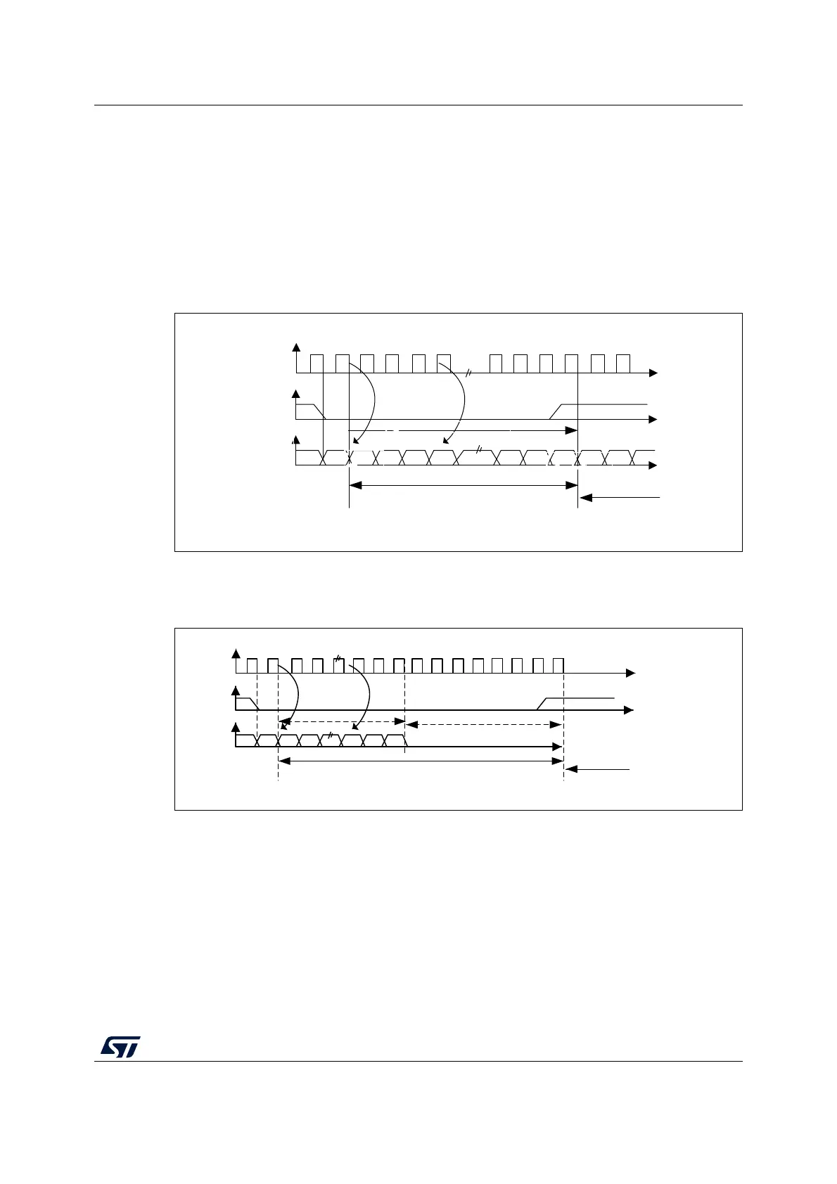
For this standard, the WS signal is used to indicate which channel is being transmitted. It is
activated one CK clock cycle before the first bit (MSB) is available.
Figure 364. I
2
S Philips protocol waveforms (16/32-bit full accuracy)
Data are latched on the falling edge of CK (for the transmitter) and are read on the rising
edge (for the receiver). The WS signal is also latched on the falling edge of CK.
Figure 365. I
2
S Philips standard waveforms (24-bit frame)
This mode needs two write or read operations to/from the SPIx_DR register.
• In transmission mode:
If 0x8EAA33 has to be sent (24-bit):
MS19591V1
CK
WS
SD
Can be 16-bit or 32-bit
MSB
MSBLSB
Channel left
Channel
right
transmission reception
MS19592V1
CK
WS
SD
Transmission Reception
24-bit data
MSB
LSB
Channel left 32-bit
Channel right
8-bit remaining 0 forced