Inter-integrated circuit (I2C) interface RM0453
1056/1450 RM0453 Rev 5
Note: t
AF(min)
/ t
AF(max)
are part of the equation only when the analog filter is enabled. Refer to the
device datasheet for t
AF
values.
The maximum t
HD;DAT
can be, respectively, 3.45, 0.9, and 0.45 µs for Standard-mode, Fast-
mode, and Fast-mode Plus. It must be lower than the maximum of t
VD;DAT
by a transition
time. This maximum must only be met if the device does not stretch the LOW period (t
LOW
)
of the SCL signal. If the clock stretches the SCL, the data must be valid by the set-up time
before it releases the clock.
The SDA rising edge is usually the worst case. In this case the previous equation becomes:
SDADEL ≤ {t
VD;DAT (max)
- t
r (max)
- t
AF (max)
- [(DNF + 4) x t
I2CCLK
]} / {(PRESC + 1) x t
I2CCLK
}.
Note: This condition can be violated when NOSTRETCH = 0, because the device stretches SCL
low to guarantee the set-up time, according to the SCLDEL value.
Refer to Table 226 for t
f
, t
r
, t
HD;DAT
, and t
VD;DAT
standard values.
• After t
SDADEL
, or after sending SDA output when the slave had to stretch the clock
because the data was not yet written in I2C_TXDR register, SCL line is kept at low level
during the setup time. This setup time is
t
SCLDEL
= (SCLDEL+ 1) x t
PRESC
, where
t
PRESC
= (PRESC+ 1) x t
I2CCLK
. t
SCLDEL
impacts the setup time t
SU;DAT
.
To bridge the undefined region of the SDA transition (rising edge usually worst case), the
user must program SCLDEL in such a way that:
{[t
r (max)
+ t
SU;DAT (min)
] / [(PRESC+ 1)] x t
I2CCLK
]} - 1 ≤ SCLDEL
Refer to Table 226 for t
r
and
t
SU;DAT
standard values.
The SDA and SCL transition time values to use are the ones in the application. Using the
maximum values from the standard increases the constraints for the SDADEL and SCLDEL
calculation, but ensures the feature, whatever the application.
Note: At every clock pulse, after SCL falling edge detection, the I2C master or slave stretches SCL
low during at least [(SDADEL + SCLDEL + 1) x (PRESC + 1) + 1] x t
I2CCLK
, in both
transmission and reception modes. In transmission mode, if the data is not yet written in
I2C_TXDR when SDADEL counter is finished, the I2C keeps on stretching SCL low until the
next data is written. Then new data MSB is sent on SDA output, and SCLDEL counter starts,
continuing stretching SCL low to guarantee the data setup time.
If NOSTRETCH = 1 in slave mode, the SCL is not stretched. Consequently the SDADEL
must be programmed so that it guarantees a sufficient setup time.
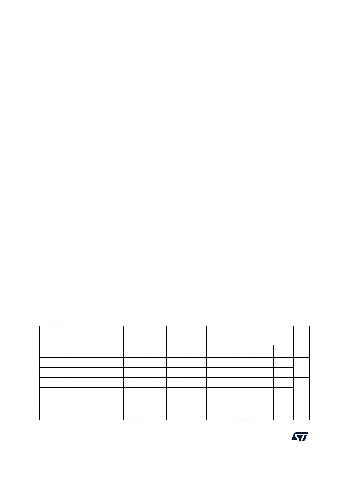
Table 226. I
2
C-SMBus specification data setup and hold times
Symbol Parameter
Standard-mode
(Sm)
Fast-mode
(Fm)
Fast-mode Plus
(Fm+)
SMBus
Unit
Min. Max Min. Max Min. Max Min. Max
t
HD;DAT
Data hold time 0-0-0 -0.3-
µs
t
VD;DAT
Data valid time - 3.45 - 0.9 - 0.45 - -
t
SU;DAT
Data setup time 250 - 100 - 50 - 250 -
ns
t
r
Rise time of both
SDA and SCL signals
- 1000 - 300 - 120 - 1000
t
f
Fall time of both
SDA and SCL signals
- 300 - 300 - 120 - 300