Analog-to-digital converter (ADC) RM0453
556/1450 RM0453 Rev 5
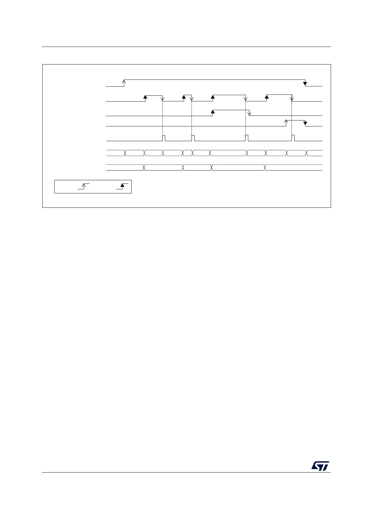
Figure 73. Wait mode conversion (continuous mode, software trigger)
1. EXTEN = 00, CONT = 1
2. CHSEL = 0x3, SCANDIR = 0, WAIT = 1, AUTOFF = 0
18.6.2 Auto-off mode (AUTOFF)
The ADC has an automatic power management feature which is called auto-off mode, and
is enabled by setting AUTOFF = 1 in the ADC_CFGR1 register.
When AUTOFF = 1, the ADC is always powered off when not converting and automatically
wakes-up when a conversion is started (by software or hardware trigger). A startup-time is
automatically inserted between the trigger event which starts the conversion and the
sampling time of the ADC. The ADC is then automatically disabled once the sequence of
conversions is complete.
Auto-off mode can cause a dramatic reduction in the power consumption of applications
which need relatively few conversions or when conversion requests are timed far enough
apart (for example with a low frequency hardware trigger) to justify the extra power and
extra time used for switching the ADC on and off.
Auto-off mode can be combined with the wait mode conversion (WAIT = 1) for applications
clocked at low frequency. This combination can provide significant power savings if the ADC
is automatically powered-off during the wait phase and restarted as soon as the ADC_DR
register is read by the application (see Figure 75: Behavior with WAIT = 1, AUTOFF = 1).
Note: Refer to the Section Reset and clock control (RCC) for the description of how to manage
the dedicated 14 MHz internal oscillator. The ADC interface can automatically switch
ON/OFF the 14 MHz internal oscillator to save power.
MSv30344V2
ADC_DR
by S/W
ADSTP
EOC
ADC state
ADSTART
EOS
CH1 CH2 STOP
CH1CH3 RDYDLYRDY
DLY
ADC_DR Read access
DLY DLY
D1
D3
D1
D2
by H/W