Debug support (DBG) RM0453
1354/1450 RM0453 Rev 5
To restart both cores simultaneously the debugger must use the CTI_APPPULSER register
in one of the CTIs. This allows the debugger to generate a pulse on any of the four CTM
channels. The channel must be connected to the DBGRESTART signal of both cores.
As shown in Table 273 and Table 275, the DBGRESTART signals to the CPUs are
connected to output 1 of the respective CTIs. The CTI_OUTENR1 register is then
programmed on each CTI to connect these outputs to an unused CTM channel (such as
channel 1).
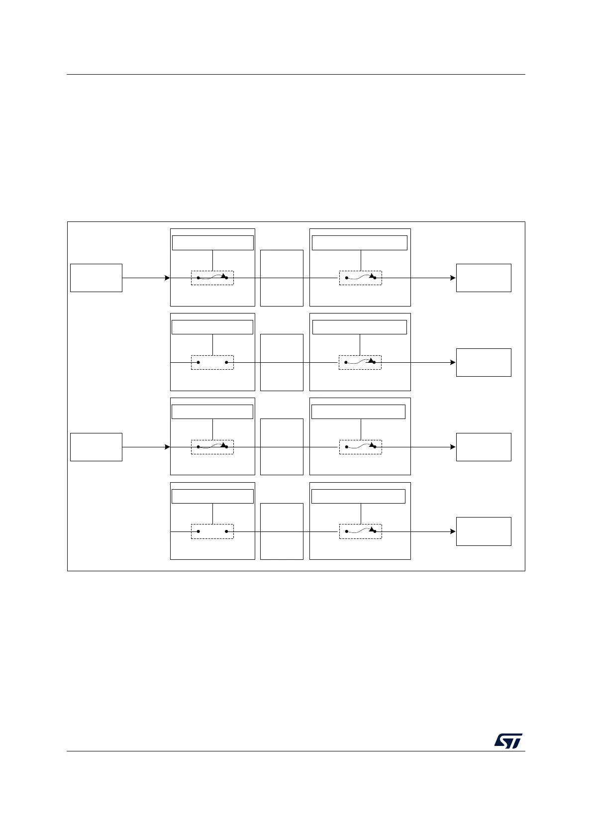
The above configuration is illustrated in Figure 390.
Figure 390. Cross trigger configuration example
The steps detailed below force the processors to restart simultaneously:
1. Clear the debug request by writing 0x01, then 0x00, to the CTI_INTACKR register in
each CTI.
2. Cause a pulse on channel 1 by writing 0x02 to the CTI_APPPULSER register in either
CTI. This generates a restart request to both processors.
Note: The debugger can also force both cores to stop simultaneously by writing 0x01 to the
CTI_APPPULSER register in either CTI, which generates a pulse on channel 0.
For more information on the CTI CoreSight component, refer to the Arm
®
CoreSight
SoC-400 Technical Reference Manual [2].
MSv60371V1
CTI_INENR0 = 0001 CTI_OUTENR0 = 0001
Channel 0
HALTED
EDBGRQ
CTI M4 CTI M0+CTM
Cortex-M4 Cortex-M0+
CTI_INENR1 = 0000 CTI_OUTENR1 = 0010
Channel 1
DBGRESTART
CTI M4 CTI M0+CTM
Cortex-M0+
CTI_INENR0 = 0001 CTI_OUTENR0 = 0001
HALTED
EDBGRQ
CTI M0+ CTI M4
Cortex-M0+ Cortex-M4
CTI_INENR1 = 0000 CTI_OUTENR1 = 0010
Channel 1
DBGRESTART
CTI M0+ CTI M4CTM
Cortex-M4
Channel 0
CTM