General-purpose timers (TIM16/TIM17) RM0453
916/1450 RM0453 Rev 5
The following procedure must be followed to re-arm the protection after a break event:
• The BKDSRM bit must be set to release the output control
• The software must wait until the system break condition disappears (if any) and clear
the SBIF status flag (or clear it systematically before re-arming)
• The software must poll the BKDSRM bit until it is cleared by hardware (when the
application break condition disappears)
From this point, the break circuitry is armed and active, and the MOE bit can be set to re-
enable the PWM outputs.
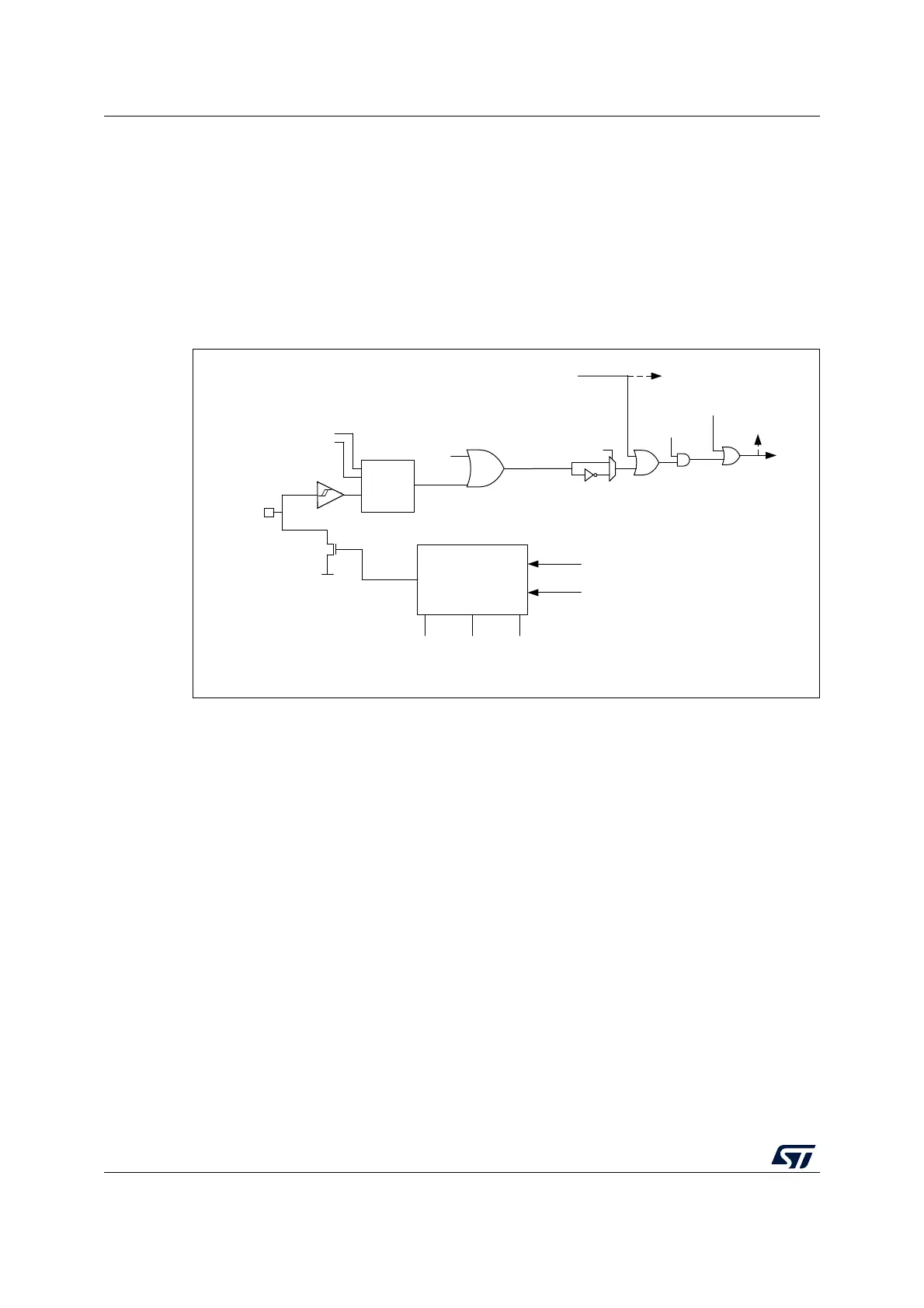
Figure 259. Output redirection
27.3.13 6-step PWM generation
When complementary outputs are used on a channel, preload bits are available on the
OCxM, CCxE and CCxNE bits. The preload bits are transferred to the shadow bits at the
COM commutation event. Thus one can program in advance the configuration for the next
step and change the configuration of all the channels at the same time. COM can be
generated by software by setting the COM bit in the TIMx_EGR register or by hardware (on
tim_trgi rising edge).
A flag is set when the COM event occurs (COMIF bit in the TIMx_SR register), which can
generate an interrupt (if the COMIE bit is set in the TIMx_DIER register) or a DMA request
(if the COMDE bit is set in the TIMx_DIER register).
The Figure 260 describes the behavior of the tim_ocx and tim_ocxn outputs when a COM
event occurs, in 3 different examples of programmed configurations.
MSv50984V1
BKIN inputs from
AF controller
BKP
BKE
BRK
request
BIF flag
SBIF flag
System break request
Peripheral
break sources
AF
controller
mode control logic
MOE BKBID BKBDSRM
BRK request
System break request
Bidirectional
Break I/O
Other break inputs
Application break requests
Vss
Bidirectional
AF input
(active low)
AF output
(open drain)
Software break
requests: BG