Analog-to-digital converter (ADC) RM0453
568/1450 RM0453 Rev 5
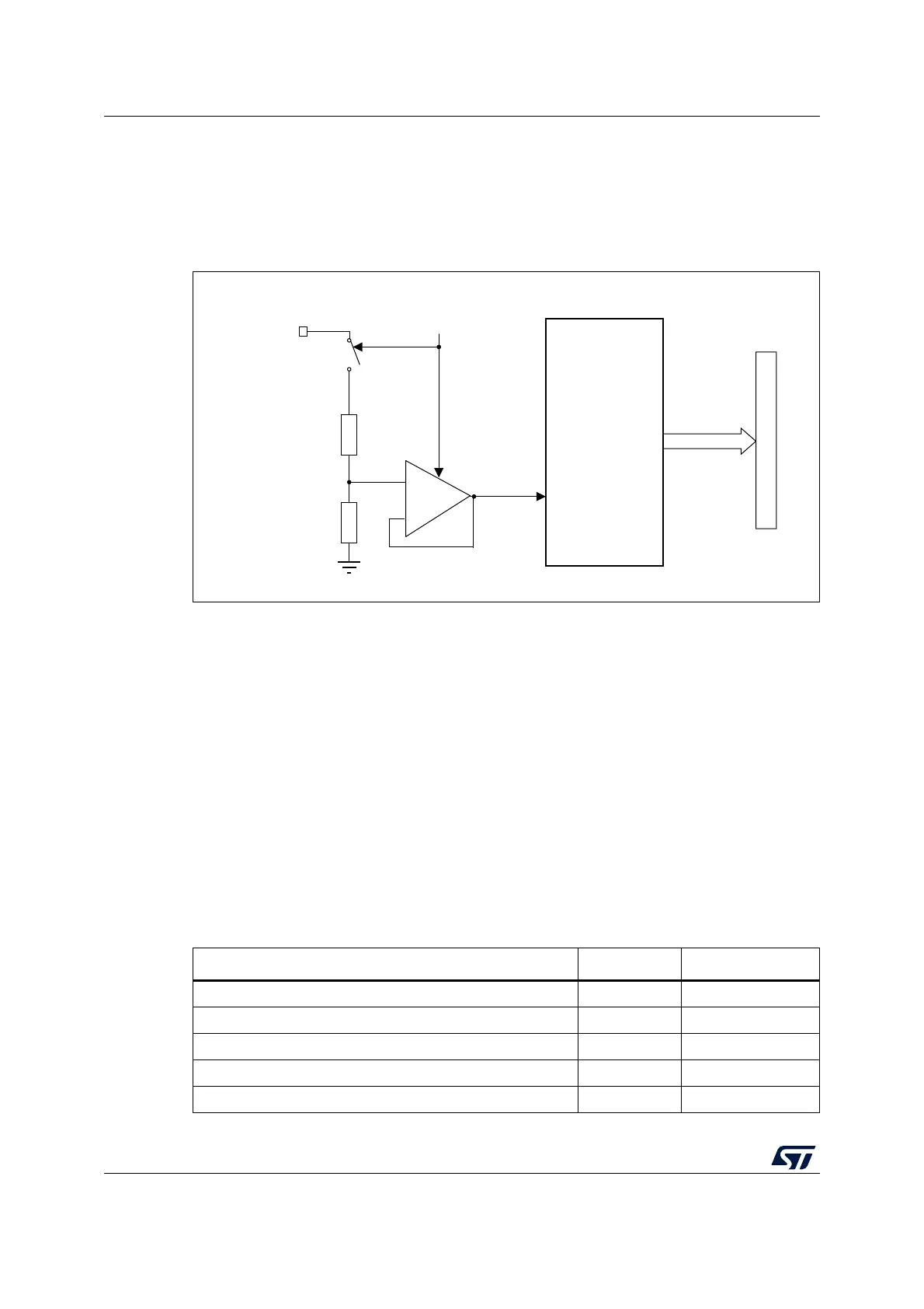
the correct operation of the ADC, the VBAT pin is internally connected to a bridge divider.
This bridge is automatically enabled when VBATEN is set, to connect V
BAT
to the ADC
V
IN
[14] input channel. As a consequence, the converted digital value is V
BAT
/3. To prevent
any unwanted consumption on the battery, it is recommended to enable the bridge divider
only when needed for ADC conversion.
Figure 85. V
BAT
channel block diagram
18.11 ADC interrupts
An interrupt can be generated by any of the following events:
• End Of Calibration (EOCAL flag)
• ADC power-up, when the ADC is ready (ADRDY flag)
• End of any conversion (EOC flag)
• End of a sequence of conversions (EOS flag)
• When an analog watchdog detection occurs (AWD1, AWD2, AWD3 flags)
• When the Channel configuration is ready (CCRDY flag)
• When the end of sampling phase occurs (EOSMP flag)
• when a data overrun occurs (OVR flag)
Separate interrupt enable bits are available for flexibility.
MSv69533V1
VBATEN control bit
Address/data bus
ADC V
IN
[14]
ADC
+
-
V
BAT
V
BAT
/3
Table 109. ADC interrupts
Interrupt event Event flag Enable control bit
End Of Calibration EOCAL EOCALIE
ADC ready ADRDY ADRDYIE
End of conversion EOC EOCIE
End of sequence of conversions EOS EOSIE
Analog watchdog 1 status bit is set AWD1 AWD1IE