RM0453 Rev 5 903/1450
RM0453 General-purpose timers (TIM16/TIM17)
944
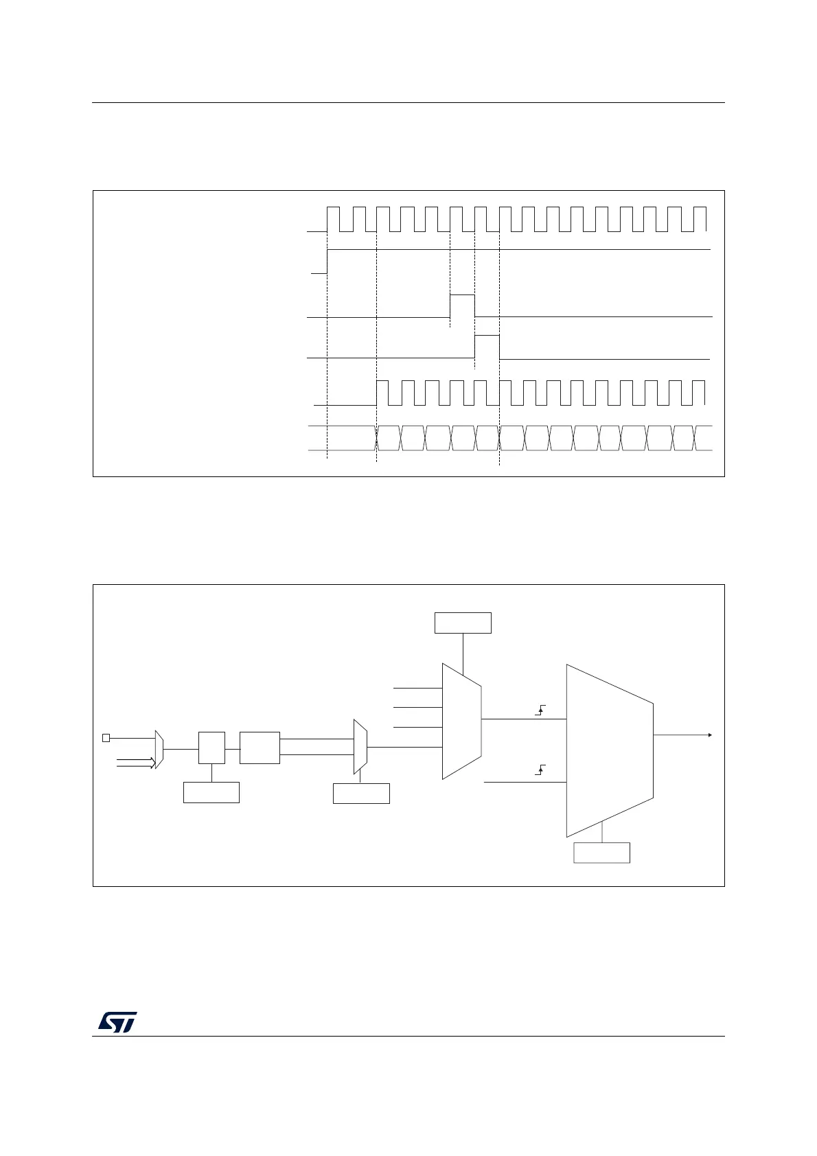
Figure 247 shows the behavior of the control circuit and the upcounter in normal mode,
without prescaler.
Figure 247. Control circuit in normal mode, internal clock divided by 1
External clock source mode 1
This mode is selected when SMS=111 in the TIMx_SMCR register. The counter can count at
each rising or falling edge on a selected input.
Figure 248. TI2 external clock connection example
For example, to configure the upcounter to count in response to a rising edge on the TI2
input, use the following procedure:
MSv31085V3
Internal clock
Counter clock = CK_CNT = CK_PSC
Counter register
CEN=CNT_EN
UG
Counter initialization (internal)
00 02
03
04 05
06 0732
33
34 35 36
31
01
MSv40935V1
External clock
mode 1
Internal clock
mode
TRGI
CK_INT
CK_PSC
TIMx_SMCR
SMS[2:0]
ITRx
TI1_ED
TI1FP1
TI2FP2
TIMx_SMCR
0
1
TIMx_CCER
CC2P
TI2F_Rising
TI2F_Falling
00110
000xx
00100
00101
Edge
detector
TS[4:0]
(internal clock)
TI2[1..15]
TI2[0]
TIMx_CCMR1
ICF[3:0]
Filter