2-50
DS35-W00 May. 2007
CLUTCHCLUTCH
CLUTCHCLUTCH
CLUTCH
TRANSMISSIONTRANSMISSION
TRANSMISSIONTRANSMISSION
TRANSMISSION
ENGINEENGINE
ENGINEENGINE
ENGINE
HSTHST
HSTHST
HST
FRONT AXLEFRONT AXLE
FRONT AXLEFRONT AXLE
FRONT AXLE
STEERINGSTEERING
STEERINGSTEERING
STEERING
BARKEBARKE
BARKEBARKE
BARKE
ELECTRICELECTRIC
ELECTRICELECTRIC
ELECTRIC
INDEXINDEX
INDEXINDEX
INDEX
HYDRAULICHYDRAULIC
HYDRAULICHYDRAULIC
HYDRAULIC
GENERALGENERAL
GENERALGENERAL
GENERAL
REAR AXLEREAR AXLE
REAR AXLEREAR AXLE
REAR AXLE
CK22/CK22H
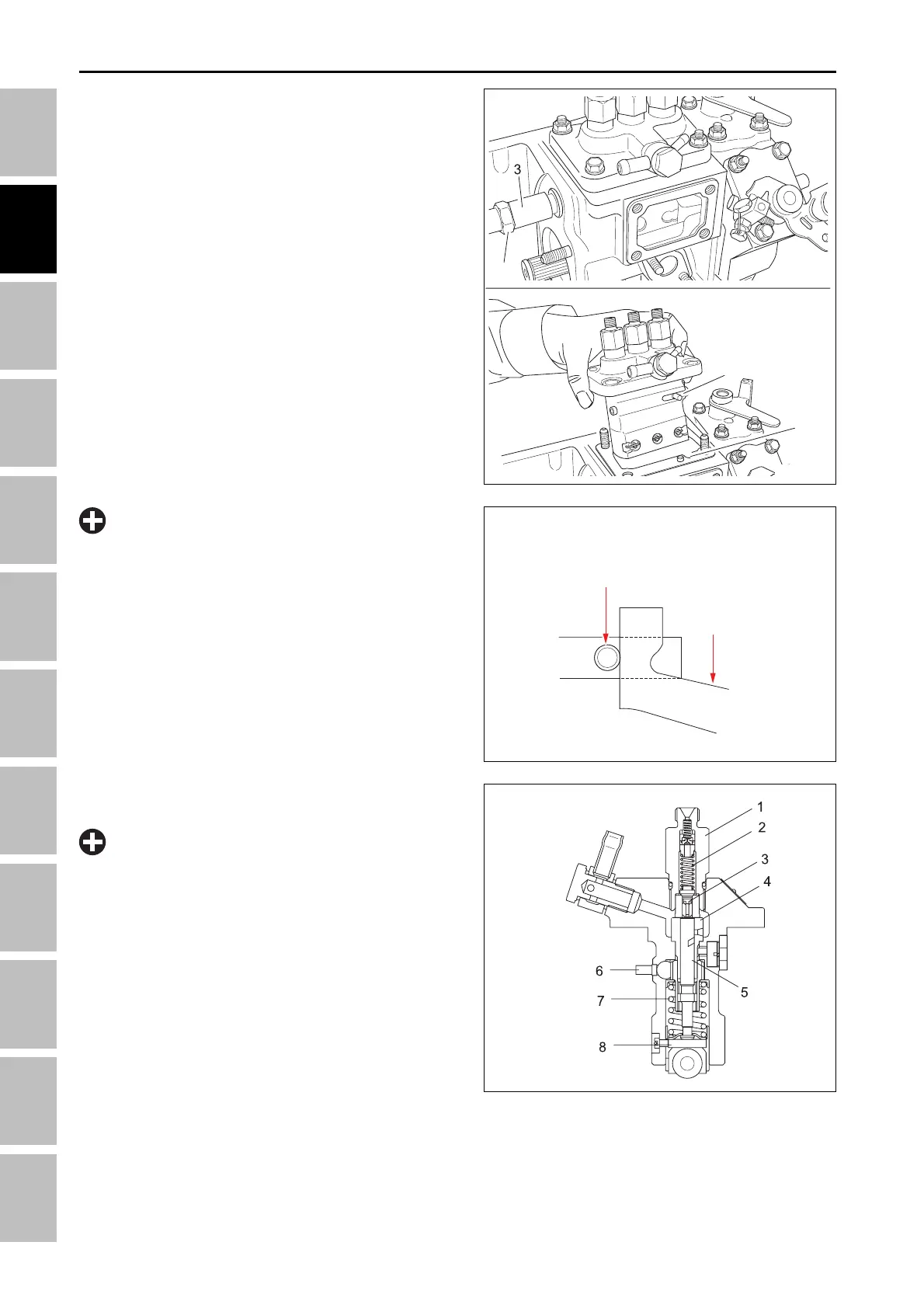
C. INJECTION PUMP
196W2H2A
(1) Pump body (5) Delivery valve
(2) Control rack (6) Tappet roller
(3) Delivery valve holder (7) Cylinder
(4) Delivery valve spring (8) Plunger
•
If replacing the pump element, the amount of fuel
injection should be adjusted on specified bench.
IMPORTANT
• Make sure that the lever of the pump control rack
is on the outer side from the fork lever 1 when
installing the pump. Otherwise, the engine can be
damaged by over speed or cannot be started.
IMPORTANT
T46W294A
Lqmhfwlrq#Sxps
Frqwuro#Odfn#Ohyhu#
Irun#Ohyhu#4
4
5
A
196W272B
4. Remove the idle limit system (3).
5. Remove the injection pump mounting bolts and nuts
(A).
6. Align the control rack pin (4) with the slot (5) on the
cylinder and remove the injection pump.
7. The injection pump should not be disassembled.
(Note for reassembling)
• Install the injection pump by aligning the control rack
with the indicated position.
• Addition or reduction of one shim (0.1 mm) delays
or advances the injection timing by 0.017 rad. (1°).
ENGINE - SERVICING