2-61
DS35-W00 May. 2007
CLUTCHCLUTCH
CLUTCHCLUTCH
CLUTCH
TRANSMISSIONTRANSMISSION
TRANSMISSIONTRANSMISSION
TRANSMISSION
ENGINEENGINE
ENGINEENGINE
ENGINE
FRONT AXLEFRONT AXLE
FRONT AXLEFRONT AXLE
FRONT AXLE
STEERINGSTEERING
STEERINGSTEERING
STEERING
BARKEBARKE
BARKEBARKE
BARKE
ELECTRICELECTRIC
ELECTRICELECTRIC
ELECTRIC
INDEXINDEX
INDEXINDEX
INDEX
HYDRAULICHYDRAULIC
HYDRAULICHYDRAULIC
HYDRAULIC
GENERALGENERAL
GENERALGENERAL
GENERAL
REAR AXLEREAR AXLE
REAR AXLEREAR AXLE
REAR AXLE
HSTHST
HSTHST
HST
CK22/CK22H
7.2 INSPECTION FOR OVERHAUL
7.2.1 CYLINDER HEAD
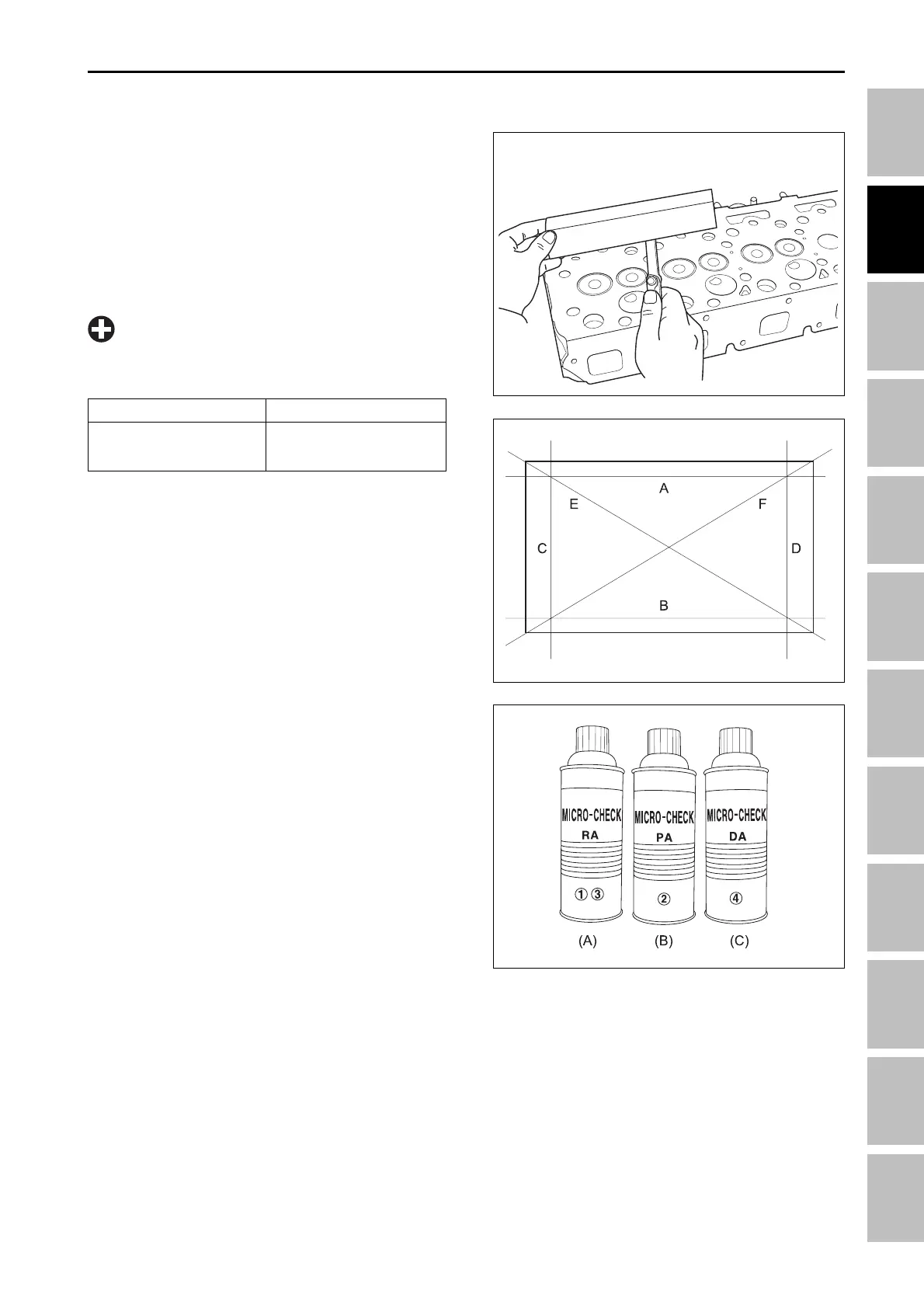
A. CYLINDER HEAD SURFACE FLATNESS
1. Thoroughly clean the cylinder head surface.
2. Place a straightedge on the cylinder head and mea-
sure the clearance with a feeler gage as shown in
the figure.
3. If the measurement exceeds the allowable limit, re-
place the cylinder head.
196W2B1A
196W2B0A
196W2A9A
Item
Flatness
Allowable limit
0.05 mm
0.0019 in.
•
Do not place the straight edge on the combustion
chamber.
IMPORTANT
B. CYLINDER HEAD SURFACE FLAW
1. Clean the cylinder head surface with the detergent
(B).
2. Spray the cylinder head surface with the red perme-
ative liquid (A).
3. Wash away the red permeative liquid on the cylin-
der head surface with the detergent (B) after ten
minutes.
4 Spray the cylinder head surface with the white de-
veloper (C).
5. If any flaw is found such as a red mark, replace the
cylinder head.
ENGINE - SERVICING