8-17
DS35-W00 May. 2007
CLUTCHCLUTCH
CLUTCHCLUTCH
CLUTCH
TRANSMISSIONTRANSMISSION
TRANSMISSIONTRANSMISSION
TRANSMISSION
ENGINEENGINE
ENGINEENGINE
ENGINE
HSTHST
HSTHST
HST
FRONT AXLEFRONT AXLE
FRONT AXLEFRONT AXLE
FRONT AXLE
STEERINGSTEERING
STEERINGSTEERING
STEERING
BARKEBARKE
BARKEBARKE
BARKE
ELECTRICELECTRIC
ELECTRICELECTRIC
ELECTRIC
INDEXINDEX
INDEXINDEX
INDEX
HYDRAULICHYDRAULIC
HYDRAULICHYDRAULIC
HYDRAULIC
GENERALGENERAL
GENERALGENERAL
GENERAL
REAR AXLEREAR AXLE
REAR AXLEREAR AXLE
REAR AXLE
CK22/CK22H
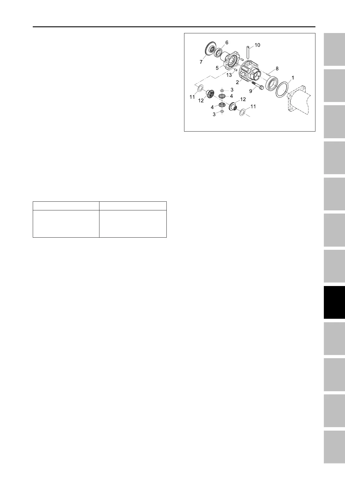
5.1.11 DISASSEMBLING DIFFERENTIAL
GEAR
1. Remove the differential case cover mounting bolts
(9) and then take out the differential case cover (5),
ball bearing (6) and spiral bevel gear (7) as a unit.
2. Remove the external snap ring (8), and then remove
the ball bearing (6) and spiral bevel gear (7) as a
unit with a puller.
3. Remove the straight pin (13).
4. Pull out the pinion shaft (10) and take out the differ-
ential pinions (4) and differential side gears (12).
NOTE:
• Arrange the parts to know their original position.
(when reassembling)
• Apply molybdenum disulfide (Three bond 1901 or
equivalent) to the inner circumferential surface of
the differential side gears (12) and differential pin-
ions (4).
• Install the pinion shaft (10) so that the hole on it
may align with the hole on differential case (2), and
install the straight pin (13).
051W730A
(1) Shim
(2) Differential case
(3) Thrust collar
(4) Differential pinion
(5) Differential case cover
(6) Ball bearing
(7) Spiral bevel gear
(8) Snap ring
(9) Screws
(10) Pinion shaft
(11) Shim
(12) Differential side gear
(13) Straight pin
Item
Differential case cover
mounting bolts
Tightening torque
48.1 ~ 55.9 Nm
4.9 ~ 5.7 Kgf-m
35.4 ~ 41.2 lbs-ft
FRONT AXLE - SERVICING