10-23
DS35-W00 May. 2007
CLUTCHCLUTCH
CLUTCHCLUTCH
CLUTCH
TRANSMISSIONTRANSMISSION
TRANSMISSIONTRANSMISSION
TRANSMISSION
ENGINEENGINE
ENGINEENGINE
ENGINE
HSTHST
HSTHST
HST
FRONT AXLEFRONT AXLE
FRONT AXLEFRONT AXLE
FRONT AXLE
STEERINGSTEERING
STEERINGSTEERING
STEERING
BARKEBARKE
BARKEBARKE
BARKE
ELECTRICELECTRIC
ELECTRICELECTRIC
ELECTRIC
INDEXINDEX
INDEXINDEX
INDEX
HYDRAULICHYDRAULIC
HYDRAULICHYDRAULIC
HYDRAULIC
GENERALGENERAL
GENERALGENERAL
GENERAL
REAR AXLEREAR AXLE
REAR AXLEREAR AXLE
REAR AXLE
CK22/CK22H
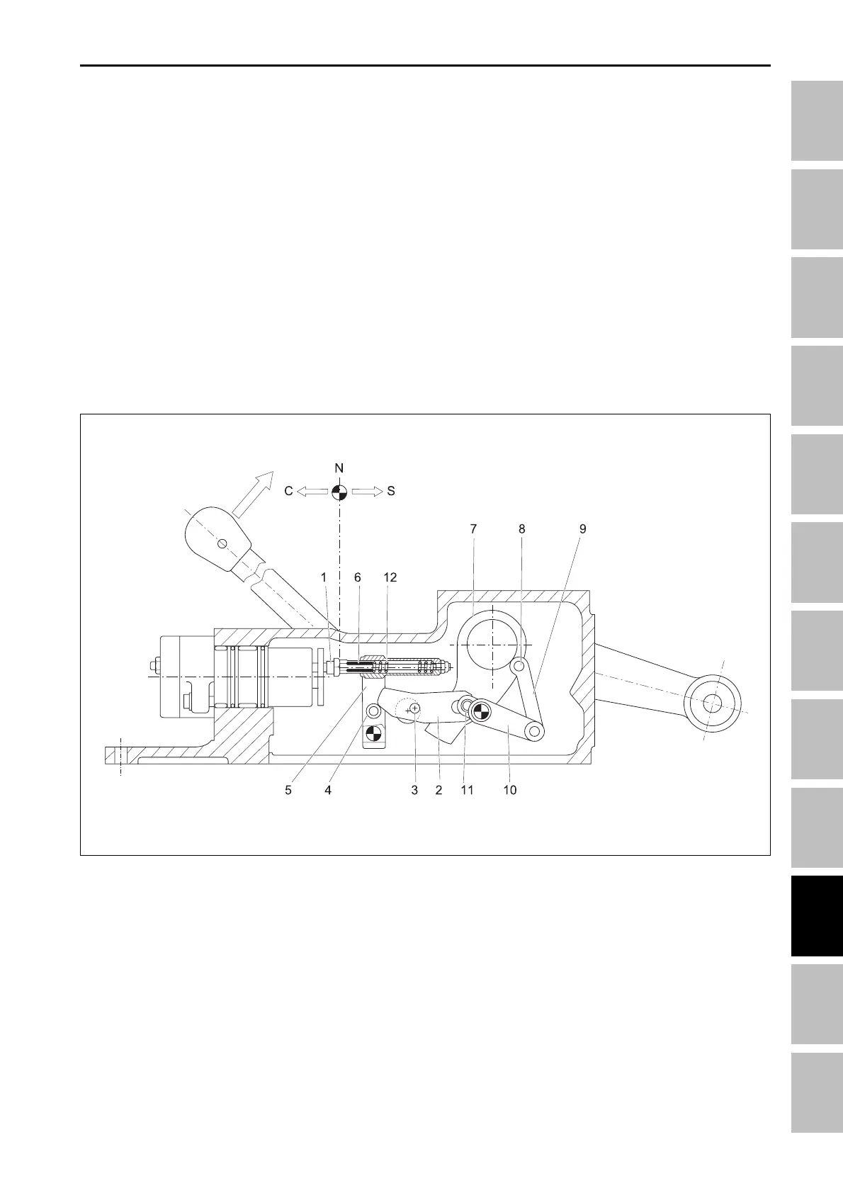
Moving the control lever “L” (In the direction of the arrow)
one can raise the arms and the internal levers affect
the Control Valve in the following way;
The cam shaft “2” welded to lever “L” turns clockwise
and rotates the cam lever “3” anticlockwise. This, push-
ing on the roller cam bowl “4”, rotates anticlockwise
the toggle lever “5” which due to the position of the
push rod “6” moves the shaft “1” of the Control Valve in
delivery phase (C) which consequently raises the arms
of the Rockshaft.
With the raising movement the crank “7” with its pin “8”
rotate anticlockwise and by means of lever “9” they ro-
tate the balance lever “10” in the same direction. The
lever “10” with its roller cam bowl “11” cause a clock-
wise rotation of the cam lever “3”.
The roller cam bowl “4” remains in contact with the
lever by effect of the springs of the shaft “1”, so the
toggle lever “5” rotates clockwise returning, by means
of the push rod “6”, the Control Valve in its neutral phase
(N) and blocking the raising of the arms.
When the arms are lowered the movement of the inter-
nal levers are in the opposite direction as described
above.
The push rod “6” is kept in a fixed position with the
toggle lever “5” by the spring seat “12”. The spring seat
“12” has the function of absorbing the extra strokes of
the internal levers when lever “L” is moved from its
lowest position to its highest position and vice-versa.
2.7.2 LINK MECHANISM IN THE LIFTING SYSTEM
A. OPERATION OF INTERNAL LEVERS IN CONTROLLED POSITION
196W936A
(1) Shaft
(2) Cam shaft
(3) Cam lever
(4) Roller cam bowl
(5) Toggle lever
(6) Push rod
(7) Crank
(8) Pin
(9) Lever
(10) Lever
(11) Roller cam bowl
(12) Spring seat
HYDRAULIC SYSTME - OPERATING PRINCIPLE