10-24
DS35-W00 May. 2007
CLUTCHCLUTCH
CLUTCHCLUTCH
CLUTCH
TRANSMISSIONTRANSMISSION
TRANSMISSIONTRANSMISSION
TRANSMISSION
ENGINEENGINE
ENGINEENGINE
ENGINE
HSTHST
HSTHST
HST
FRONT AXLEFRONT AXLE
FRONT AXLEFRONT AXLE
FRONT AXLE
STEERINGSTEERING
STEERINGSTEERING
STEERING
BARKEBARKE
BARKEBARKE
BARKE
ELECTRICELECTRIC
ELECTRICELECTRIC
ELECTRIC
INDEXINDEX
INDEXINDEX
INDEX
HYDRAULICHYDRAULIC
HYDRAULICHYDRAULIC
HYDRAULIC
GENERALGENERAL
GENERALGENERAL
GENERAL
REAR AXLEREAR AXLE
REAR AXLEREAR AXLE
REAR AXLE
CK22/CK22H
B. ROCKSHAFT ADJUSTMENT
In case of revision of the Rockshaft or Control Valve it is
opportune to do again the adjustments in the sequence
found below.
1. SENSITIVITY ADJUSTMENT OF THE CON-
TROL VALVE.
2. ADJUSTMENT OF THE CONTROL LEVER WITH
RESPECT TO THE ROCKSHAFT ARMS.
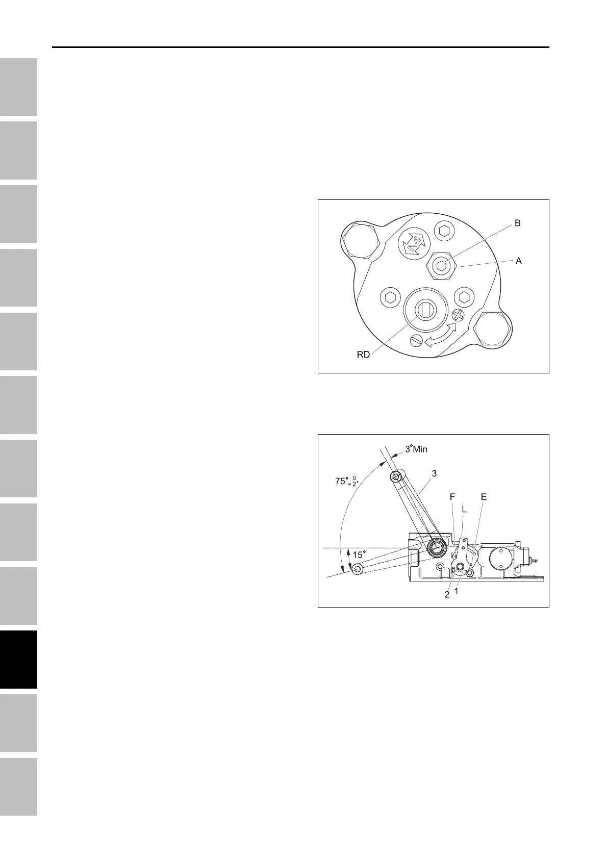
a. Sensitivity adjustment.
Position the rockshaft lifting arms, with a weight applied,
so that they reach about half their angular movement
range.
In this way the Control Valve is positioned in its neutral
phase.
Loosen nut “A” and turn the embedded hexagonal
screw “B” in an anti-clockwise direction until the lifting
arms start swaying continuously.
With a slow movement stop the movement of the arms
by rotating screw “B” in a clockwise direction.
When the arms remain blocked in their position, which
can be controlled with the relevant instrument posi-
tioned on the end of the lifting arm, rotate clockwise the
screw “B” for 1/2 ~ 3/4 of a turn max. And block the
position with the self-locking nut “A”.
In this way the Control Valve is sensitivity adjusted.
196W937A
b. Adjustment of position control lever
Completely lower the arms and apply a weight.
The adjustment is carried out in order to establish the
maximum raised position of the rockshaft lifting arms.
Loosen the fastening screw “1” so as to free the lever
“L” from the position control shaft “2”.
Raise the lever “L” all the way toward backstop “F” with-
out rotating shaft “2”
With a 13 mm open end wrench, rotate slowly in an
anticlockwise direction the position control shaft “2” so
as to raise the arms. Continue the rotation until reach-
ing the degree of 75
-
2
°
(The maximum raised position).
Take care to maintain the position control shaft “2”
blocked and the lever “L” against the backstop “F”.
Fix the lever to the shaft by tightening completely the
clamp with the fastening screw “1”.
Control by raising and lowering the lever “L” 3 or 4
times so that the arms always reach the same position
at their highest position.
After concluding the adjustment, always verify that there
exists a security distance (minimum 3°) between the
maximum raised position and the position of the me-
chanical backstop.
If the lifting arms reach the position of the mechanical
backstop, the safety valve (relief valve 160 kgf/cm²) in-
tervenes to keep from damaging the pump.
196W938B
(1) Screw
(2) Shaft 2
(3) Lifting arm in mechanic lock
0
HYDRAULIC SYSTME - OPERATING PRINCIPLE