10-31
DS35-W00 May. 2007
CLUTCHCLUTCH
CLUTCHCLUTCH
CLUTCH
TRANSMISSIONTRANSMISSION
TRANSMISSIONTRANSMISSION
TRANSMISSION
ENGINEENGINE
ENGINEENGINE
ENGINE
HSTHST
HSTHST
HST
FRONT AXLEFRONT AXLE
FRONT AXLEFRONT AXLE
FRONT AXLE
STEERINGSTEERING
STEERINGSTEERING
STEERING
BARKEBARKE
BARKEBARKE
BARKE
ELECTRICELECTRIC
ELECTRICELECTRIC
ELECTRIC
INDEXINDEX
INDEXINDEX
INDEX
HYDRAULICHYDRAULIC
HYDRAULICHYDRAULIC
HYDRAULIC
GENERALGENERAL
GENERALGENERAL
GENERAL
REAR AXLEREAR AXLE
REAR AXLEREAR AXLE
REAR AXLE
CK22/CK22H
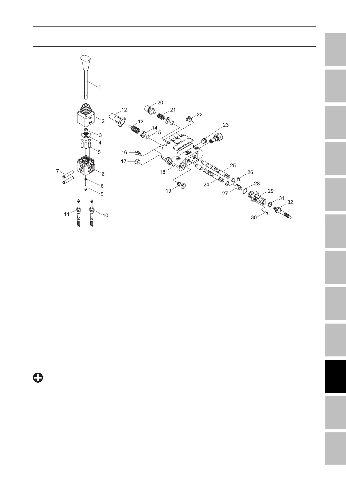
•
The float spool (24) and spool (25) are not inter-
changeable and will only work in their respective
bores.
Ensure that the spools are inserted into the proper
bores during reassembly.
IMPORTANT
(1) Lever knob
(2) Rubber
(3) Nut
(4) Selector
(5) Pin
(6) Body
(7) Ring
(8) Washer
(9) Screw
(10) Cable
(11) Cable
(12) End cap
196W944B
(13) Spool control kit
(14) Ring
(15) O-ring
(16) Plug
(17) Plug
(18) Body
(19) Plug
(20) End cap
(21) Spool control kit
(22) Plug
4.2.2 JOY-STICK VALVE DISASSEMBLY
5. Disassemble the spool (25) in the same manner
as the float spool using step through 4.
6. Remove the load check plugs (17) with O-rings,
springs and load check poppets from the check
valve ports.
Inspection:
1. Inspect the spools and the spool bores for pitting,
scratches, of excess wear. If found defective, re-
place the Joy-stick valve assembly.
2. Check that the spool moves freely in the spool bore.
3. Inspect the load check valve poppets for pitting or
scratches.
4. Inspect all springs for distortion. Replace if found
to be defective.
5. Replace all O-rings and seals during reassembly
and lightly lubricate with petroleum jelly.
1. Loosen the nuts (32) of cable and remove the
screws (30), rod pins (26) and cables (11, 10).
2. Remove End cap screws, End cap (12) from the
float spool (24).
3. Remove End cap screws, End cap (20) from the
spool (25).
4. Gently slide the float spool (24) with spool control kit
(13), Ring (14) and O-ring (15) out of the valve body.
(23) Plug
(24) Spool
(25) Spool
(26) Red pin
(27) Joint
(28) O-ring
(29) Flange
(30) Screw
(31) Washer
(32) Nut
HYDRAULIC SYSTME - SERVICING