2-36
DS35-W00 May. 2007
CLUTCHCLUTCH
CLUTCHCLUTCH
CLUTCH
TRANSMISSIONTRANSMISSION
TRANSMISSIONTRANSMISSION
TRANSMISSION
ENGINEENGINE
ENGINEENGINE
ENGINE
HSTHST
HSTHST
HST
FRONT AXLEFRONT AXLE
FRONT AXLEFRONT AXLE
FRONT AXLE
STEERINGSTEERING
STEERINGSTEERING
STEERING
BARKEBARKE
BARKEBARKE
BARKE
ELECTRICELECTRIC
ELECTRICELECTRIC
ELECTRIC
INDEXINDEX
INDEXINDEX
INDEX
HYDRAULICHYDRAULIC
HYDRAULICHYDRAULIC
HYDRAULIC
GENERALGENERAL
GENERALGENERAL
GENERAL
REAR AXLEREAR AXLE
REAR AXLEREAR AXLE
REAR AXLE
CK22/CK22H
Item
Valve clearance
Factory spec.
0.15 mm
0.006 in.
Cylinder No.
Valve
Checking
3
IN. EX.
cz
2
IN. EX.
zc
1
IN. EX.
cc
196W254B
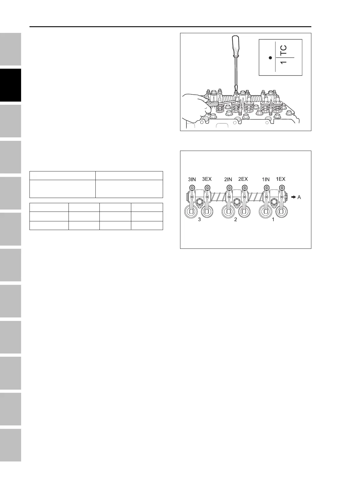
5.3 VALVE CLEARANCE
1. Remove the cylinder head cover and the timing win-
dow cover on the flywheel housing and all glow
plugs.
2. Turn the flywheel and align the 1TC to mark with the
timing mark of window on the flywheel housing to
position the 1st cylinder valves at the top dead cen-
ter during compression.
3. Measure the clearance at the valves marked with c
in the table below with a feeler gauge.
4. If the clearance is not within the factory
specifications, turn the adjusting screw to adjust.
5. Turn the flywheel just one turn to position the 1st
cylinder valves at the top dead center during overlap.
6. Measure the clearance at the valves marked with z
in the table below with a feeler gauge.
7. If the clearance is not within the factory
specifications, adjust.
196W253B
(A) Gear case
ENGINE - MEASUREMENT AND ADJUSTMENT