11-7
DS35-W00 May. 2007
TRANSMISSIONTRANSMISSION
TRANSMISSIONTRANSMISSION
TRANSMISSION
ENGINEENGINE
ENGINEENGINE
ENGINE
HSTHST
HSTHST
HST
FRONT AXLEFRONT AXLE
FRONT AXLEFRONT AXLE
FRONT AXLE
STEERINGSTEERING
STEERINGSTEERING
STEERING
BARKEBARKE
BARKEBARKE
BARKE
ELECTRICELECTRIC
ELECTRICELECTRIC
ELECTRIC
INDEXINDEX
INDEXINDEX
INDEX
HYDRAULICHYDRAULIC
HYDRAULICHYDRAULIC
HYDRAULIC
GENERALGENERAL
GENERALGENERAL
GENERAL
REAR AXLEREAR AXLE
REAR AXLEREAR AXLE
REAR AXLE
CLUTCHCLUTCH
CLUTCHCLUTCH
CLUTCH
CK22/CK22H
1.3.3 WIRE IDENTIFICATION
A. WIRE CODE
The codes used in wiring diagram represent the size
of wire and the color of insulating cover.
Example) AVS(SS, X) 0.85GR
A: Low-tension cables for automobiles
V: Vinyl insulated
S: Thin-wall type
SS: Very thin-wall type
X: Cross-linked
0.85: Cross sectional area of wire (0.85 mm
2
)
G: Base color of insulating cover
R: Stripe color on the base color
ELECTRIC SYSTEM -
CIRCUIT AND COMPONENT LOCATION
• If the wire color is striped, the base color is given
first, followed by the stripe color as shown below:
Ex) LW = Blue with White stripe
CAUTION
196WA72A
• This table is based on the ambient temperature of
40°C and the allowable current can be slightly
changed by the external factors such as ambient
temperature.
CAUTION
The allowable current for wire is specified by cross
sectional area of wire, and it is marked on the wire
cover. To avoid wire damage, a proper size (sufficient
capacity) of wire for electric load should be used when
installing a optional electric equipment. The thickness
of wire is determined by considering ambient
temperature, wire length, current continuity time, and
vibration.
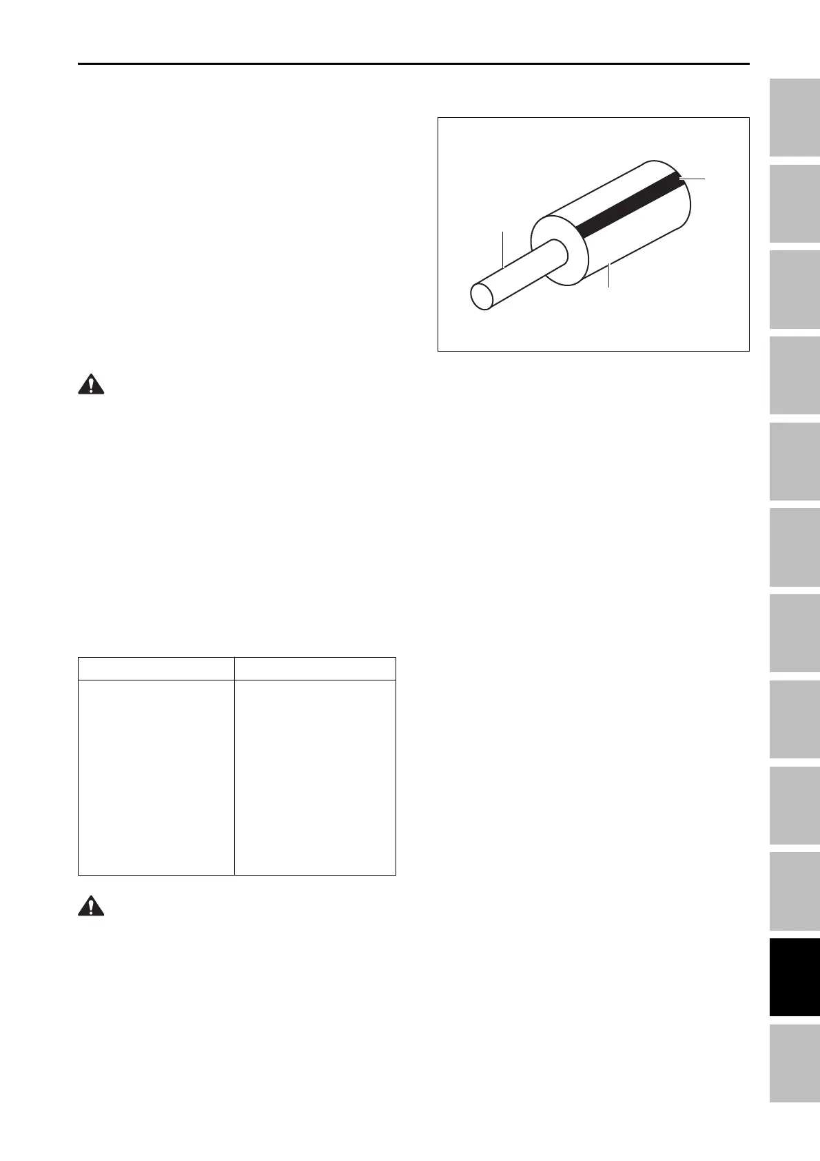
B. WIRE SIZE
(1) Wire (3) Base color
(2) Stripe Color
Allowable current
11 A
14 A
19 A
26 A
37 A
44 A
50 A
60 A
66 A
Specification
AVSS 0.5
AVSS 0.85
AVSS 1.25
AVSS 2.0
AVS 3.0
AVSS 3.0
AVS 5.0
AVSS 5.0
AVS 8.0
2
3
1