8-16
DS35-W00 May. 2007
CLUTCHCLUTCH
CLUTCHCLUTCH
CLUTCH
TRANSMISSIONTRANSMISSION
TRANSMISSIONTRANSMISSION
TRANSMISSION
ENGINEENGINE
ENGINEENGINE
ENGINE
HSTHST
HSTHST
HST
FRONT AXLEFRONT AXLE
FRONT AXLEFRONT AXLE
FRONT AXLE
STEERINGSTEERING
STEERINGSTEERING
STEERING
BARKEBARKE
BARKEBARKE
BARKE
ELECTRICELECTRIC
ELECTRICELECTRIC
ELECTRIC
INDEXINDEX
INDEXINDEX
INDEX
HYDRAULICHYDRAULIC
HYDRAULICHYDRAULIC
HYDRAULIC
GENERALGENERAL
GENERALGENERAL
GENERAL
REAR AXLEREAR AXLE
REAR AXLEREAR AXLE
REAR AXLE
CK22/CK22H
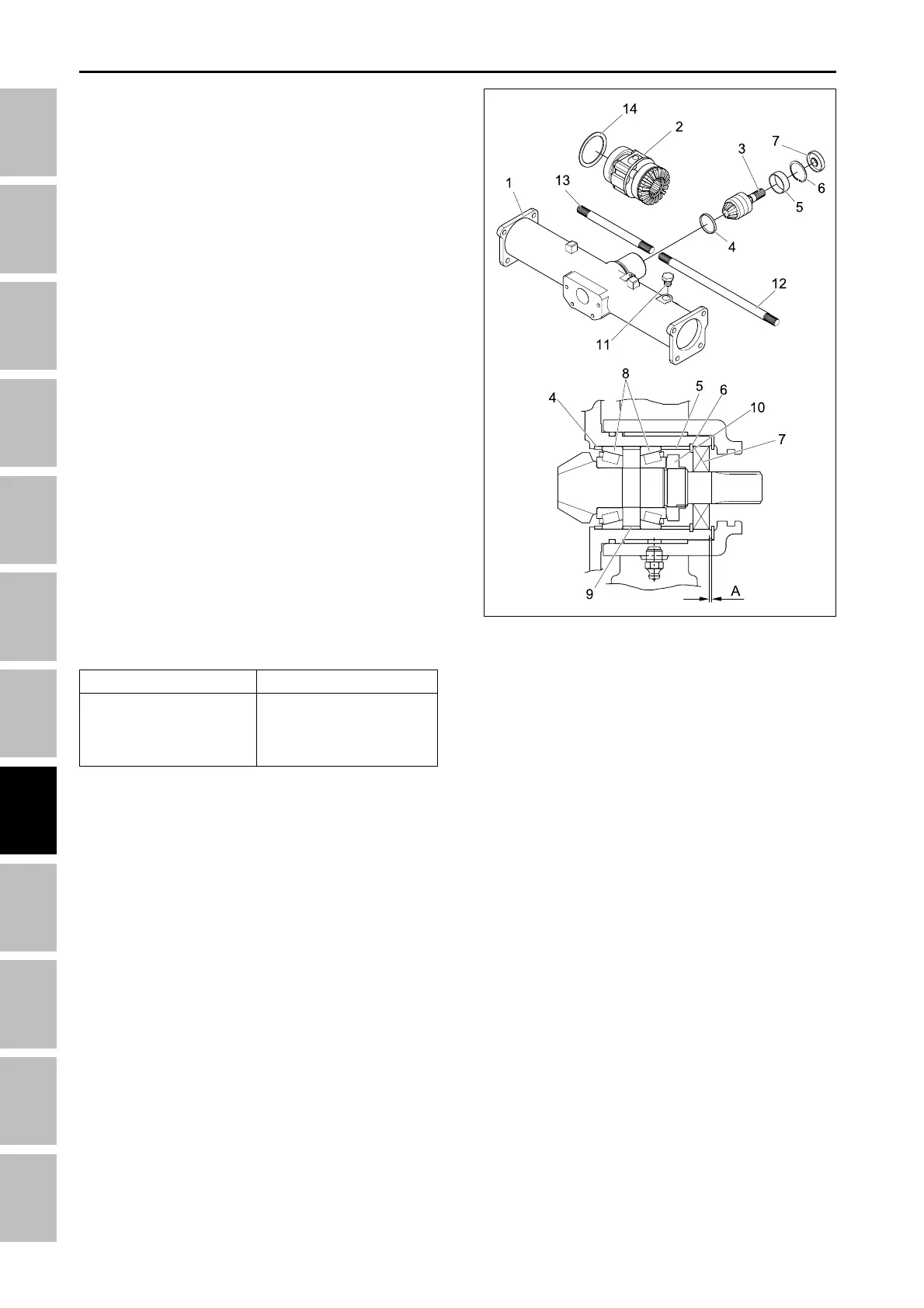
5.1.10 DISASSEMBLING SPIRAL BEVEL
PINION SHAFT AND DIFFERENTIAL
GEAR ASSEMBLY
1. Take out the differential yoke shaft (12), (13) both
sides.
2. Remove the oil seal (7) and internal snap ring (6).
3. Remove the plug (11), and then tap out the spiral
bevel pinion shaft (3) by the brass rod and hammer.
4. Take out the differential gear assembly (2), ball bear-
ing and shim (14) from right side of front axle case
(1).
5. Remove the stake of lock nut (10), and then remove
the lock nut (10).
6. Remove the taper roller bearings (8).
(When reassembling)
• Replace the lock nut (10), oil seal (7) and plug (11)
with new ones.
• Apply grease to the oil seal (6).
• Install the same shims and collars before they are
removed.
• Install the taper roller bearings correctly, noting their
direction, and apply gear oil to them.
• When press-fitting a oil seat (6), observe the di-
mension “A” described in the figure.
• Stake the lock nut (10) firmly.
• Tighten up the lock nut (10) until the turning force of
the spiral bevel pinion shaft reaches the factory
specifications. (See page 8-20)
(A) 1 mm (0.039 in.)
(1) Front axle case
(2) Differential gear assemly
(3) Spiral bevel pinion shaft
(4) Adjusting collar
(5) Collar
(6) Snap ring
(7) Oil seal
(8) Taper roller bearings
(9) Collar
(10) Lock nut
(11) Plug
(12) Differential yoke shaft RH
(13) Differential yoke shaft LH
(14) Shim
196W728A
Item
Spiral bevel pinion
shaft turning torque
Factory spec.
0.98 ~ 1.18 Nm
0.1 ~ 0.12 kgf-m
0.72 ~ 0.89 lbs-ft
FRONT AXLE - SERVICING