11-22
DS35-W00 May. 2007
CLUTCHCLUTCH
CLUTCHCLUTCH
CLUTCH
TRANSMISSIONTRANSMISSION
TRANSMISSIONTRANSMISSION
TRANSMISSION
ENGINEENGINE
ENGINEENGINE
ENGINE
HSTHST
HSTHST
HST
FRONT AXLEFRONT AXLE
FRONT AXLEFRONT AXLE
FRONT AXLE
STEERINGSTEERING
STEERINGSTEERING
STEERING
BARKEBARKE
BARKEBARKE
BARKE
ELECTRICELECTRIC
ELECTRICELECTRIC
ELECTRIC
INDEXINDEX
INDEXINDEX
INDEX
HYDRAULICHYDRAULIC
HYDRAULICHYDRAULIC
HYDRAULIC
GENERALGENERAL
GENERALGENERAL
GENERAL
REAR AXLEREAR AXLE
REAR AXLEREAR AXLE
REAR AXLE
CK22/CK22H
1
2
3
4
5
AM
ACC
OFF
ACC
ON
GL
ST
ON GL ST
196WA20B
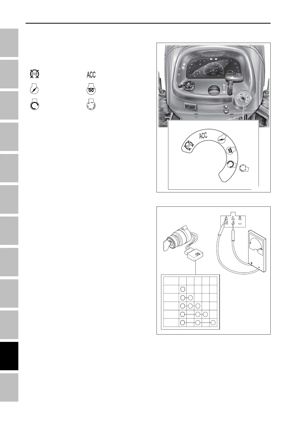
4.2 STARTING SYSTEM
4.2.1 KEY SWITCH
The key switch is located on the right side of the
operator’s console. The five positions of the switch are:
196WA19B
A. KEY SWITCH TESTING
Disconnect the key switch from the wiring harness
connector. Use an ohmmeter to test the switch.
• With the key in the “OFF” position, continuity will not
exist between any of the terminals, not shown.
• With the key in the “ACCESSORY” position, there
will be continuity between the (AM-BATTERY) and
(ACCESSORY) terminals of the switch, and (A) and
(B) of the connector.
• With the key in the “ENGINE PREHEAT” position,
there will be continuity between the (BATTERY) and
(HEAT) terminal of the switch, and (A) and (C) or (D)
of the connector.
• With the switch in the “ON” position, there will be
continuity between (BATTERY) and (ON) terminal of
the switch, and (A) and (D) of the connector.
• With the key in the “START” position, there will be
continuity between the (BATTERY) and (START) ter-
minals of the switch, and (A) and (E) or (D) of the
connector. If the test results are not as outlined
above, replace the key switch.
(A) Battery (D) Key ON
(B) Accessory (E) Start
(C) Engine heat
NOTE:
• All positions are in a clockwise rotation.
• The “START” position is spring loaded to return to
“ON” position.
ELECTRIC SYSTEM - SERVICING
.....
Off (1)
.....
Key On (3)
.....
Start (5)
(CK22-USA)
.....
Accessory (2)
.....
Pre-heat (4)
.....
Start (5)
(CK22-EU)