5-11
DS35-W00 May. 2007
CLUTCHCLUTCH
CLUTCHCLUTCH
CLUTCH
TRANSMISSIONTRANSMISSION
TRANSMISSIONTRANSMISSION
TRANSMISSION
ENGINEENGINE
ENGINEENGINE
ENGINE
HSTHST
HSTHST
HST
FRONT AXLEFRONT AXLE
FRONT AXLEFRONT AXLE
FRONT AXLE
STEERINGSTEERING
STEERINGSTEERING
STEERING
BARKEBARKE
BARKEBARKE
BARKE
ELECTRICELECTRIC
ELECTRICELECTRIC
ELECTRIC
INDEXINDEX
INDEXINDEX
INDEX
HYDRAULICHYDRAULIC
HYDRAULICHYDRAULIC
HYDRAULIC
GENERALGENERAL
GENERALGENERAL
GENERAL
REAR AXLEREAR AXLE
REAR AXLEREAR AXLE
REAR AXLE
CK22/CK22H
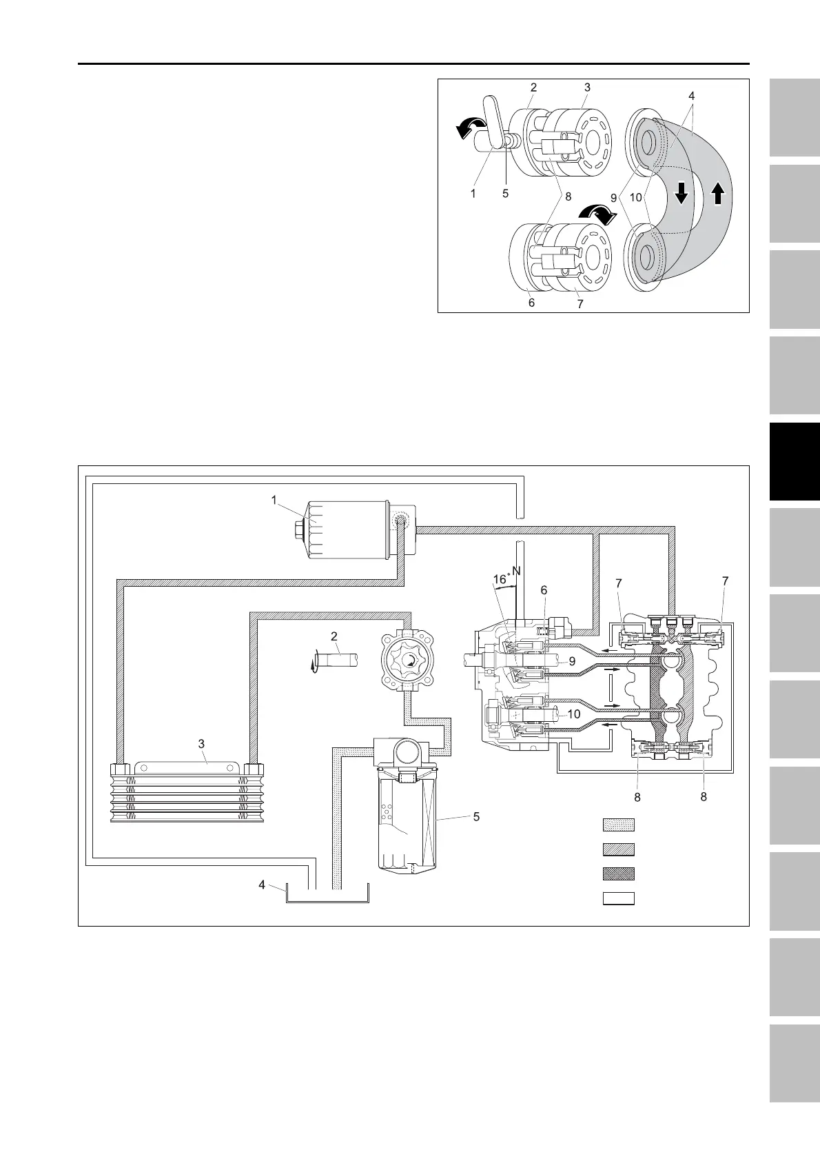
2.4.2 FORWARD
Move the swash plate control lever to the left, the run-
ning swash plate will be angled as illustrated. As the
cylinder block is connected with the input shaft, it ro-
tates with the input shaft. When the cylinder block ro-
tates by passing the pump port A, oil comes in through
piston port and continues to rotate, the oil will be dis-
charged through pump port B.
When the oil is supplied to motor port B, oil pressur-
izes the piston by increasing the pressure. The piston
pushes against the fixed swash plate causing it to slide
down.
The piston tends to rotate the cylinder block because it
is attached on the cylinder block. The cylinder block
rotates output shaft.
If the cylinder block continues to rotate, the oil will be
discharged through motor port A with low pressure and
then return to pump port A.
196W4A5A
(1) Swach plate angle control lever
(2) Running swash plate
(3) Cylinder block (7) Cylinder block
(4) Main circuit (8) Piston
(5) Trunnion shaft (9) Port B
(6) Fixed swash plate (10) Prot A
196W493A
(1) HST hydraulic filter
(2) Input shaft
(3) Oil cooler
(4) Oil tank (T/M case)
(5) Hydraulic oil filter
(6) Charge relief valve
(7) Neutral valve
(8) High-pressure relief valve
Intake pressure
Charge pressure
High pressure
Case pressure
(9) PTO shaft
(10) Output shaft
HST - OPERATING PRINCIPLE