2-15
DS35-W00 May. 2007
CLUTCHCLUTCH
CLUTCHCLUTCH
CLUTCH
TRANSMISSIONTRANSMISSION
TRANSMISSIONTRANSMISSION
TRANSMISSION
ENGINEENGINE
ENGINEENGINE
ENGINE
HSTHST
HSTHST
HST
FRONT AXLEFRONT AXLE
FRONT AXLEFRONT AXLE
FRONT AXLE
STEERINGSTEERING
STEERINGSTEERING
STEERING
BARKEBARKE
BARKEBARKE
BARKE
ELECTRICELECTRIC
ELECTRICELECTRIC
ELECTRIC
INDEXINDEX
INDEXINDEX
INDEX
HYDRAULICHYDRAULIC
HYDRAULICHYDRAULIC
HYDRAULIC
GENERALGENERAL
GENERALGENERAL
GENERAL
REAR AXLEREAR AXLE
REAR AXLEREAR AXLE
REAR AXLE
CK22/CK22H
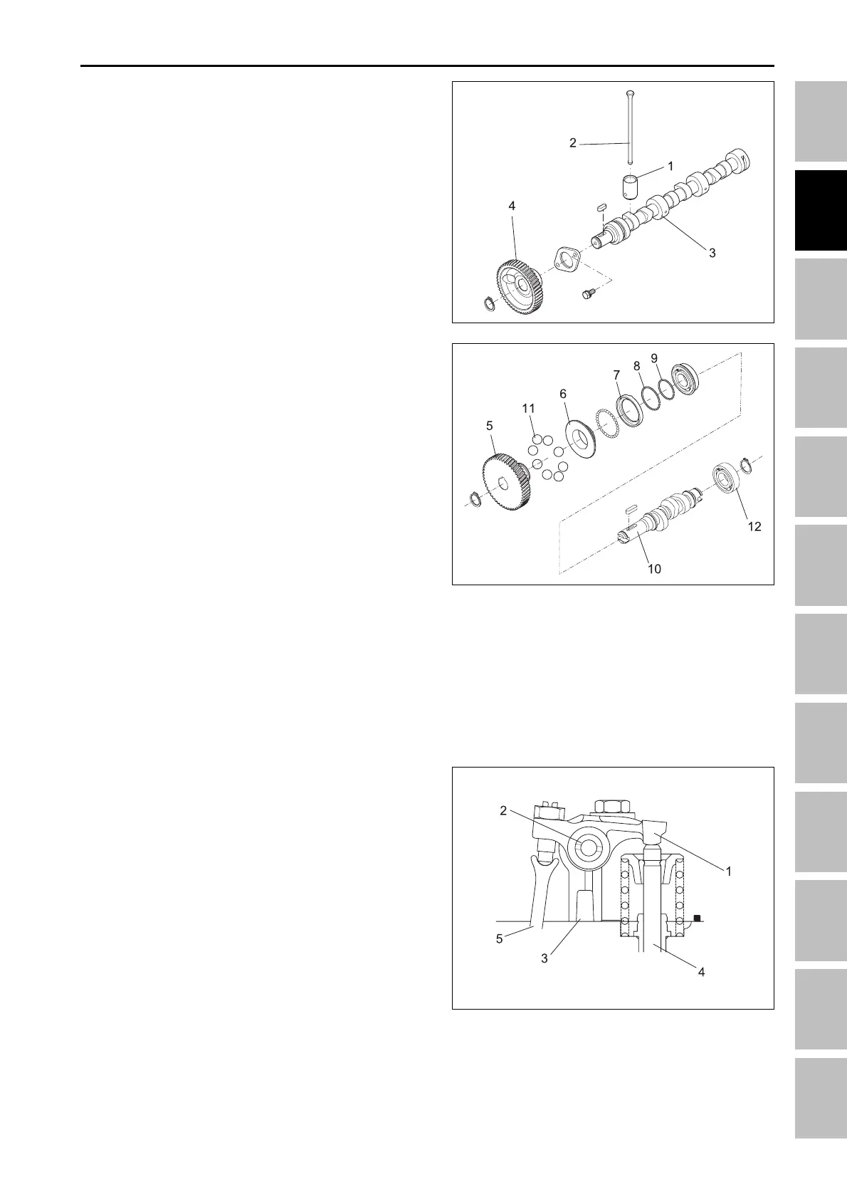
3.1.6 CAMSHAFT AND FUEL CAMSHAFT
The camshaft is made of special cast iron; the journal
and cam sections are chromed to resist wear. The jour-
nal sections are force-lubricated. The fuel camshaft
controls the reciprocating movement of the injection
pump, and is also equipped with a ball to control the
governor. Fuel camshaft is made of carbon steel and
cam sections are covered and tempered to provide
greater wear resistance.
(1) Tappet (7) Governor ball case
(2) Push rod (8) Cir-clip
(3) Camshaft (9) Cir-clip
(4) Camshaft gear (10) Fuel camshaft
(5) Injection pump gear (11) Ball
(6) Governor sleeve (12) Ball bearing
196W214A
196W215A
3.1.7 ROCKER ARM ASSEMBLY
The rocker arm assembly includes the rocker arms,
arm brackets and arm shafts and converts the move-
ment of the push rods to open/close of the inlet and
exhaust valves. Valve controlled timing must be ad-
justed with screws on the rocker arms. Lubrication oil
is pressurized through arm bearings and the entire
system is lubricated.
(1) Rocker arm
(2) Rocker arm shaft
(3) Rocker arm bracket
196W216B
(4) Valve
(5) Push rod
ENGINE - OPERATING PRINCIPLE