10-38
DS35-W00 May. 2007
CLUTCHCLUTCH
CLUTCHCLUTCH
CLUTCH
TRANSMISSIONTRANSMISSION
TRANSMISSIONTRANSMISSION
TRANSMISSION
ENGINEENGINE
ENGINEENGINE
ENGINE
HSTHST
HSTHST
HST
FRONT AXLEFRONT AXLE
FRONT AXLEFRONT AXLE
FRONT AXLE
STEERINGSTEERING
STEERINGSTEERING
STEERING
BARKEBARKE
BARKEBARKE
BARKE
ELECTRICELECTRIC
ELECTRICELECTRIC
ELECTRIC
INDEXINDEX
INDEXINDEX
INDEX
HYDRAULICHYDRAULIC
HYDRAULICHYDRAULIC
HYDRAULIC
GENERALGENERAL
GENERALGENERAL
GENERAL
REAR AXLEREAR AXLE
REAR AXLEREAR AXLE
REAR AXLE
CK22/CK22H
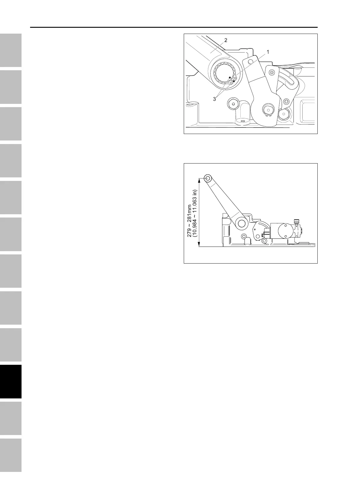
4.4 LIFT ARMS REMOVAL AND IN-
STALLATION
1. Remove external snap ring (1) from end splined
shaft.
2. Use wire brush to clean paint and any dirt from end
of splined shaft.
3. Mark end of splined shaft and lift arm (2) for ease of
reassembly.
4. Use soft face hammer to tap inside of lift arm to
remove lift arm from splined shaft.
Installation:
1. Align marks on splined shaft and lift arm and slide
lift arms onto splines on rockshaft. If marks are not
available (new lift arms or shaft) use following
procedure:
• Rotate rockshaft manually until upper mechani-
cal stop is reached.
• Align lift arm, so that ball end center measures
279 ~ 281 mm (10.984 ~ 11.063 in.) from base,
with splines on rockshaft and install.
• Secure with C-clip.
2. Align second lift arm with first and install on
rockshaft. Secure with C-clip. Check angle of both
lift arms, they should be within 5° of each other. If
not, reset lift arms on splines and/or replace
rockshaft.
3. Once rockshaft assembly is installed on vehicle be
sure to perform lift arm upper stop adjustment
procedure. (See “Adjustment of position control lever”
on page 9-25.)
196W959A
196W960A
(1) Snap Ring (3) Marks
(2) Lift Arm
HYDRAULIC SYSTME - SERVICING