2-77
DS35-W00 May. 2007
CLUTCHCLUTCH
CLUTCHCLUTCH
CLUTCH
TRANSMISSIONTRANSMISSION
TRANSMISSIONTRANSMISSION
TRANSMISSION
ENGINEENGINE
ENGINEENGINE
ENGINE
FRONT AXLEFRONT AXLE
FRONT AXLEFRONT AXLE
FRONT AXLE
STEERINGSTEERING
STEERINGSTEERING
STEERING
BARKEBARKE
BARKEBARKE
BARKE
ELECTRICELECTRIC
ELECTRICELECTRIC
ELECTRIC
INDEXINDEX
INDEXINDEX
INDEX
HYDRAULICHYDRAULIC
HYDRAULICHYDRAULIC
HYDRAULIC
GENERALGENERAL
GENERALGENERAL
GENERAL
REAR AXLEREAR AXLE
REAR AXLEREAR AXLE
REAR AXLE
HSTHST
HSTHST
HST
CK22/CK22H
B. DISASSEMBLING AND ASSEMBLING
ff
ff
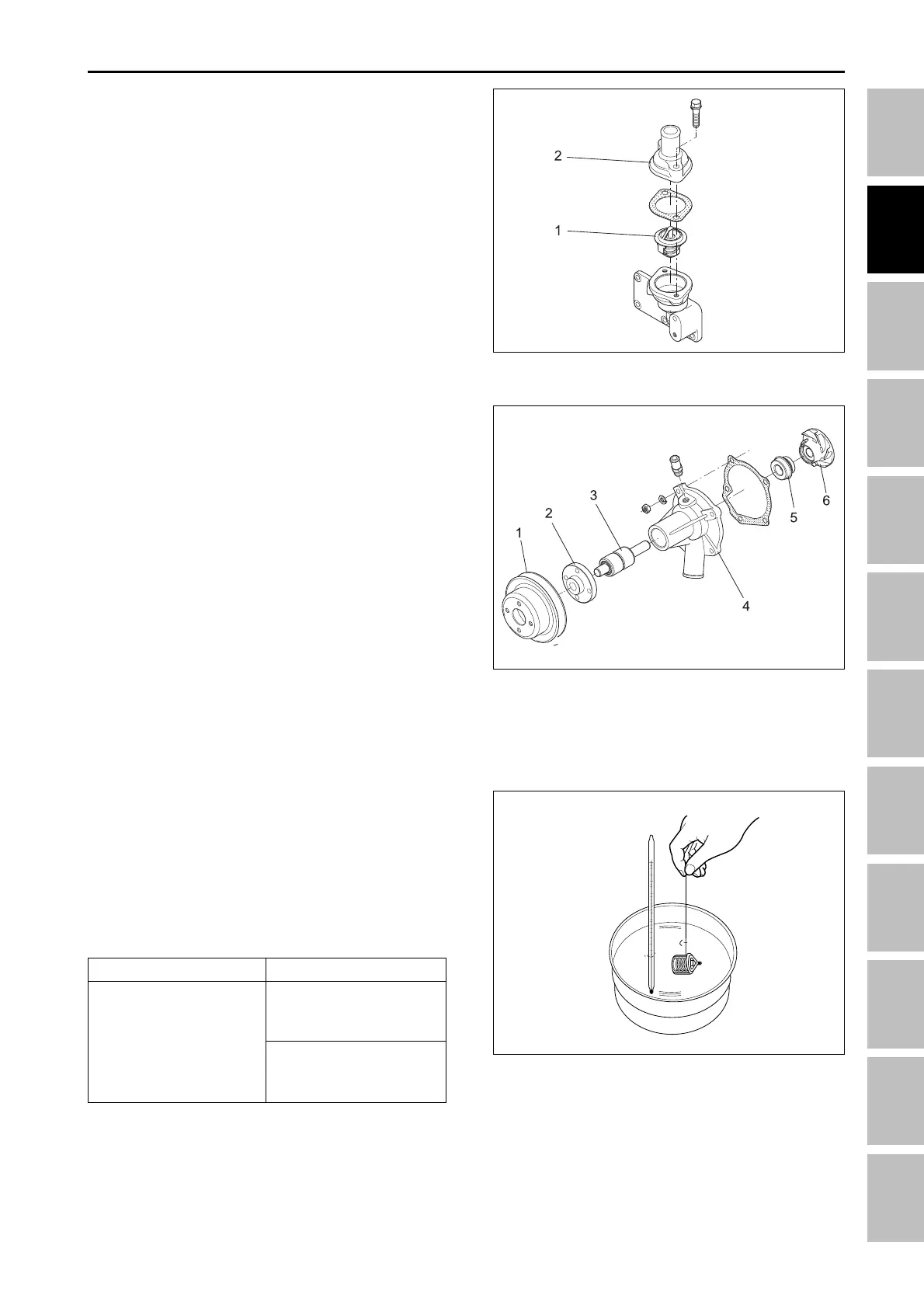
f THERMOSTAT
1. Remove the thermostat cover (2).
2. Take out the thermostat (1).
(When reassembling)
• Apply liquid gasket (Three Bond 1,215 or equivalent)
to the gasket.
(1) Thermostat (2) Thermostat Cover
ff
ff
f WATER PUMP
1. Remove the fan and fan pulley(1).
2. Remove the water pump body from gear case cover.
3. Remove the water pump flange (2).
4. Remove the impeller and water pump shaft (3).
5. Remove the impeller from the water pump shaft.
6. Remove the mechanical seal (5).
(When reassembling)
• Replace the mechanical seal (5) with new one.
• If changing the water pump, change the whole one.
• If disassembling the water pump, check to see the
clearance between the water pump impeller and
body.
C. THERMOSTAT
1. Suspend the thermostat in the water by a string with
its end inserted between the valve and seat.
2. Heating the water gradually, read the temperatures
when the valve open and leave the string and when
the valve opens approx. 8 mm (0.315 in.)
3. If the measurements are not within the factory
specification, replace the thermostat.
196W2G4A
196W2G3B
196W2G2A
Item
Opening temperature
Factory spec.
82 ± 1.5°C
(180 ± 3°F)
at beginning
lower than 95°C (203°F)
at 8 mm (0.315 in.)
of opening.
(1) Fan pullry (4) Water pump body
(2) Flange (5) Mechanical seal
(3) Pump shaft (6) Impeller
ENGINE - SERVICING