4-24
DS35-W00 May. 2007
CLUTCHCLUTCH
CLUTCHCLUTCH
CLUTCH
TRANSMISSIONTRANSMISSION
TRANSMISSIONTRANSMISSION
TRANSMISSION
ENGINEENGINE
ENGINEENGINE
ENGINE
HSTHST
HSTHST
HST
FRONT AXLEFRONT AXLE
FRONT AXLEFRONT AXLE
FRONT AXLE
STEERINGSTEERING
STEERINGSTEERING
STEERING
BARKEBARKE
BARKEBARKE
BARKE
ELECTRICELECTRIC
ELECTRICELECTRIC
ELECTRIC
INDEXINDEX
INDEXINDEX
INDEX
HYDRAULICHYDRAULIC
HYDRAULICHYDRAULIC
HYDRAULIC
GENERALGENERAL
GENERALGENERAL
GENERAL
REAR AXLEREAR AXLE
REAR AXLEREAR AXLE
REAR AXLE
CK22/CK22H
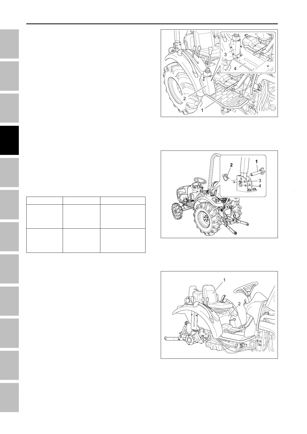
4.7 SEPARATING ROPS AND TIRES
1. Remove the lynch pin (2) and the lock pin (1) from
the ROPS frame.
2. Loosen the bolt (3) and remove the pin (4).
3. Place to fix the jack to the bottom of the rear axle.
4. Remove the nuts & bolts from the wheel.
Item
ROPS lock
bolt
Rear wheel
bolt
Tightening torque
48.1 ~ 55.8 Nm
4.9 ~ 5.7 kgf-m
35.5 ~ 41.2 lb-ft
215 Nm
22 kgf-m
160 lb-ft
Spec.
M10
M16
4.8 SEAT
1. Remove the the cover under the seat and then re-
move the seat (1).
2. Remove the return spring and the front cover (2).
196W433A
196W4D4A
(1) Lock pin (3) Bolt
(2) Lynch pin (4) Pin
(1) Seat
(2) Lynch pin
4.6 STEP
1. Remove the step mat (LH/RH) (1).
2. Remove the joystick mounting bolts and disconnect
the cover (2).
3. Remove the frame (3).
4. Remove the step (LH/RH) (4).
196W4D1A
(1) Step mat (3) Frame
(2) Cover (4) Step
TRANSMISSION - SERVICING