5-5
DS35-W00 May. 2007
CLUTCHCLUTCH
CLUTCHCLUTCH
CLUTCH
TRANSMISSIONTRANSMISSION
TRANSMISSIONTRANSMISSION
TRANSMISSION
ENGINEENGINE
ENGINEENGINE
ENGINE
HSTHST
HSTHST
HST
FRONT AXLEFRONT AXLE
FRONT AXLEFRONT AXLE
FRONT AXLE
STEERINGSTEERING
STEERINGSTEERING
STEERING
BARKEBARKE
BARKEBARKE
BARKE
ELECTRICELECTRIC
ELECTRICELECTRIC
ELECTRIC
INDEXINDEX
INDEXINDEX
INDEX
HYDRAULICHYDRAULIC
HYDRAULICHYDRAULIC
HYDRAULIC
GENERALGENERAL
GENERALGENERAL
GENERAL
REAR AXLEREAR AXLE
REAR AXLEREAR AXLE
REAR AXLE
CK22/CK22H
2.2 STRUCTURE
2.2.1 FEATURES
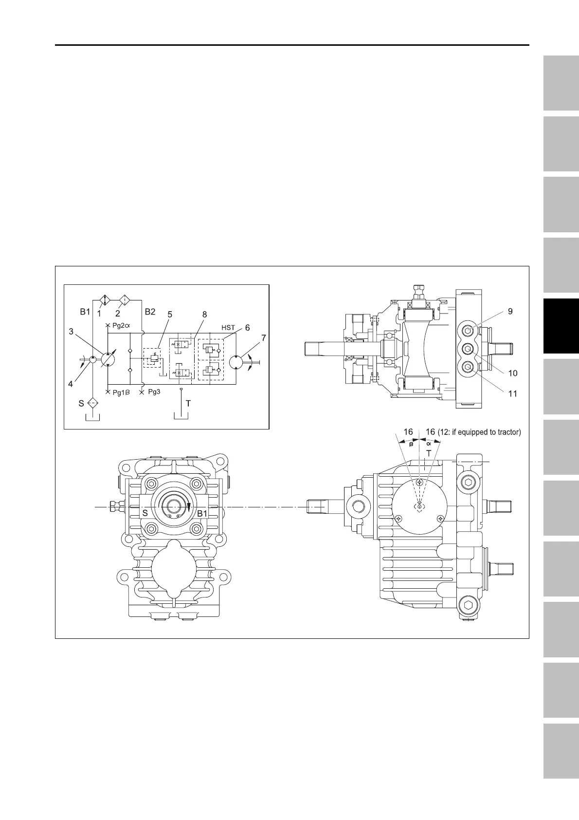
1. HST (Hydraulic Transmission)
• HST is directly linked to transmission case, and it
consists of one variable displacement piston pump
with connected to closed circuit, one fixed type pis-
ton motor, oil filter, charge pump, charge relief valve,
check valve, high-pressure relief valve and neutral
valve.
2.2.2 APPEARANCE OF HYDRAULIC TRANSMISSION AND CIRCUIT
196W498B
(1) Oil cooler
(2) HST filter
(3) Variable piston pump
(4) Charge pump
(5) Neutral valve
(6) High PRE. valve (LH, RH)
(7) Fixed piston motor
(8) Charge relief V/V
(9) Reverse high pressure port
(10) Charge pressure port
(11) Forward high pressure port
• The pump converts the input rotation from engine
to hydraulic pressure that lets the motor operate;
accordingly the motor produces the output rotation.
• The rotational direction and speed of output shaft is
dependent on the changes of hydraulic oil path that
moves the swash plate controlled by HST pedal in
footwall.
• Various hydraulic devices share the oil tank, but HST
uses dedicated oil filter due to it needs especially
clean oil.
HST - OPERATING PRINCIPLE