10-22
DS35-W00 May. 2007
CLUTCHCLUTCH
CLUTCHCLUTCH
CLUTCH
TRANSMISSIONTRANSMISSION
TRANSMISSIONTRANSMISSION
TRANSMISSION
ENGINEENGINE
ENGINEENGINE
ENGINE
HSTHST
HSTHST
HST
FRONT AXLEFRONT AXLE
FRONT AXLEFRONT AXLE
FRONT AXLE
STEERINGSTEERING
STEERINGSTEERING
STEERING
BARKEBARKE
BARKEBARKE
BARKE
ELECTRICELECTRIC
ELECTRICELECTRIC
ELECTRIC
INDEXINDEX
INDEXINDEX
INDEX
HYDRAULICHYDRAULIC
HYDRAULICHYDRAULIC
HYDRAULIC
GENERALGENERAL
GENERALGENERAL
GENERAL
REAR AXLEREAR AXLE
REAR AXLEREAR AXLE
REAR AXLE
CK22/CK22H
k
j
A
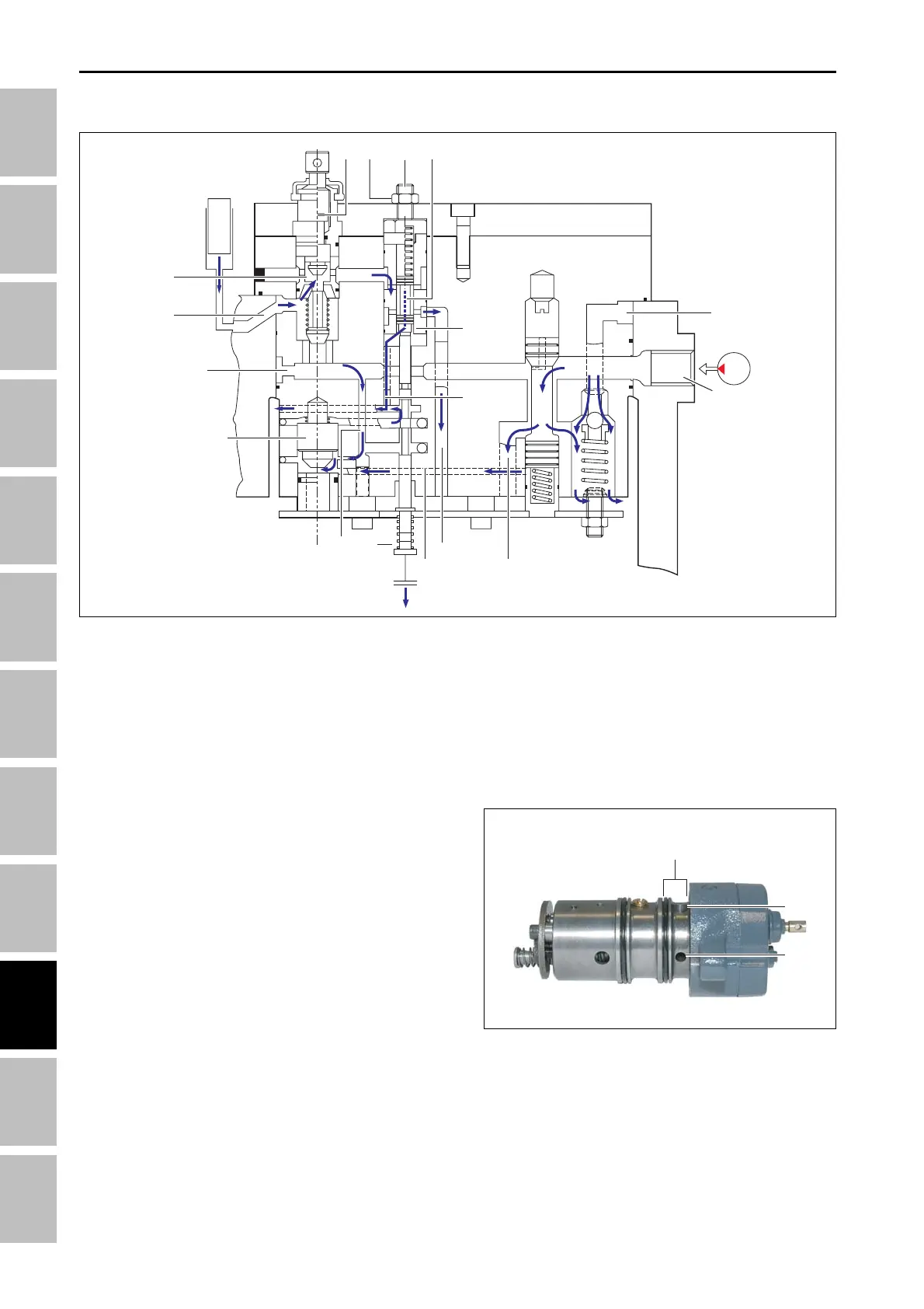
D. LOWERING
Lowering:
When the control spool (1) moves downward, the fluid
passage between (a) and (b) ports are blocked as
same as when the valve is in the neutral position.
The hydraulic fluid drawn through the (b) port is drained
through the drain hole (c) on the bottom of the regula-
tor piston. The hydraulic fluid drawn through the (a)
port is supplied to the bottom of the pilot through the
passage (d) to lift the pilot valve. Then, this fluid is
drained as the fluid on the bottom of the regulator pis-
ton is drained through the passage (e).
As the control spool moves downward, the discharge
valve (2) moves downward by the upper spring to open
the drain passage. Therefore, the lifting arm is low-
ered as the fluid in the lifting cylinder is drained through
the drain passage (f).
The small oil hole (g) on the bottom of the discharge
valve is to drain the fluid from the top of the discharge
valve when the exhaust valve is closed again.
The fluid on the top of the discharge valve is drained
through this hole and the fluid passage (h).
Lowering speed adjust valve:
When turning the handle of the lowering speed adjust
valve (3) from outside, the size of the fluid passage (i)
is adjusted and, therefore, the lowering speed of the
lifting arm can be adjusted. When turning the handle
clockwise to its end, passage is completely blocked
and the lifting arm can be locked at a certain position.
Pilot valve (12):
The pilot valve (4) delays the initial fluid flow by open-
ing or closing the control spool to help the smooth
lifting arm operation.
Control sensitivity adjustment:
The opening timing of the spool (1) can be adjusted by
adjusting the position of the spool with unscrewing the
lock nut (5) and then adjusting the bolt (6). It means
that the sensitivity of the control spool can be adjusted.
Refer to “Measurement and adjustment” in this chap-
ter for detailed information.
Safety valve:
The section (A) in the figure is the chamber that sup-
plies the cylinder with oil. The hole (j) in the sectional
view is connected to the hole (k) which is connected to
the safety valve.
If the hydraulic lifting arm is applied with abnormal im-
pact or excessive load, the MLS valve can be damaged.
However, the hydraulic fluid in the lifting cylinder is
drawn to the (k) port through the port (j) by the outer
force. Then, it opens the safety valve, which is set to
200 kgf/cm
2
, is drained to the outside.
T46WA32A
T46WA33A
2
6
1
4
e c
f
d
3
b
k
i
5
a
g
h
HYDRAULIC SYSTME - OPERATING PRINCIPLE