2-62
DS35-W00 May. 2007
CLUTCHCLUTCH
CLUTCHCLUTCH
CLUTCH
TRANSMISSIONTRANSMISSION
TRANSMISSIONTRANSMISSION
TRANSMISSION
ENGINEENGINE
ENGINEENGINE
ENGINE
HSTHST
HSTHST
HST
FRONT AXLEFRONT AXLE
FRONT AXLEFRONT AXLE
FRONT AXLE
STEERINGSTEERING
STEERINGSTEERING
STEERING
BARKEBARKE
BARKEBARKE
BARKE
ELECTRICELECTRIC
ELECTRICELECTRIC
ELECTRIC
INDEXINDEX
INDEXINDEX
INDEX
HYDRAULICHYDRAULIC
HYDRAULICHYDRAULIC
HYDRAULIC
GENERALGENERAL
GENERALGENERAL
GENERAL
REAR AXLEREAR AXLE
REAR AXLEREAR AXLE
REAR AXLE
CK22/CK22H
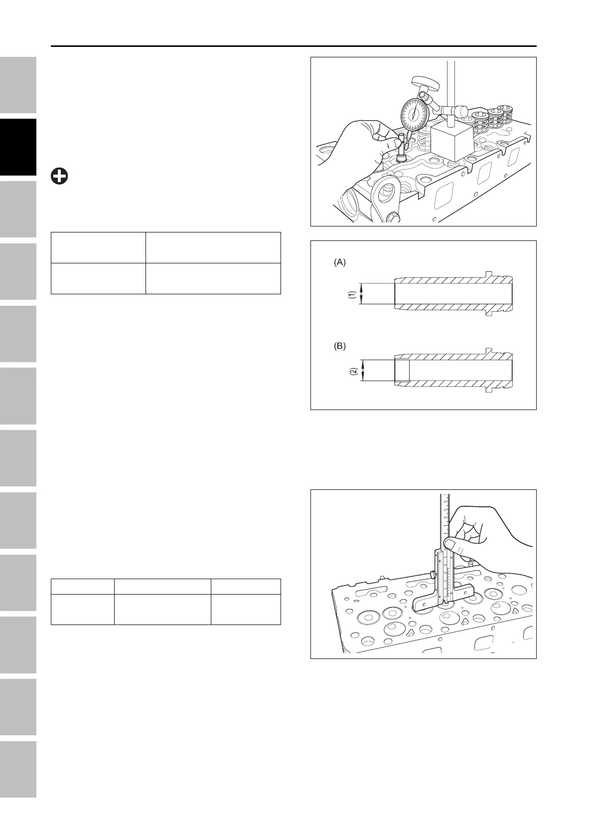
C. VALVE STEM CLEARANCE
1. Remove the carbon from the valve guide.
2. Measure the valve stem O.D. with an outside
micrometer.
3. Measure the valve guide I.D. of cylinder head, and
calculate the clearance.
4. If the measurement exceeds the allowable limit,
replace the valve guide or the valve.
Reference value
Allowable limit
0.035 ~ 0.065 mm
0.0014 ~ 0.0026 in.
0.1 mm
0.004 in.
(A) Finishing size of inlet valve guide
(B) Finishing size of exhaust valve guide
(1) 7.010 ~ 7.025 mm 0.2760 ~ 0.2766 in.
(2) 7.010 ~ 7.025 mm 0.2760 ~ 0.2766 in.
196W2B2B
196W2B3B
196W2B4A
Item
Valve
recessing
Factory spec.
0.9 ~ 1.1 mm
0.035 ~ 0.043 in.
Allowable limit
1.3 mm
0.051 in.
D. VALVE RECESSING
1. Clean the cylinder head, the valve face and the seat.
2. Insert the valve in the guide.
3. Measure the valve recessing with a depth gauge.
4. If the recessing exceeds the allowable limit, replace
the valve and check the valve seating.
•
When changing the valve guide, be sure to ream
as the figure indicates after inserting the valve
guide.
IMPORTANT
ENGINE - SERVICING