2-70
DS35-W00 May. 2007
CLUTCHCLUTCH
CLUTCHCLUTCH
CLUTCH
TRANSMISSIONTRANSMISSION
TRANSMISSIONTRANSMISSION
TRANSMISSION
ENGINEENGINE
ENGINEENGINE
ENGINE
HSTHST
HSTHST
HST
FRONT AXLEFRONT AXLE
FRONT AXLEFRONT AXLE
FRONT AXLE
STEERINGSTEERING
STEERINGSTEERING
STEERING
BARKEBARKE
BARKEBARKE
BARKE
ELECTRICELECTRIC
ELECTRICELECTRIC
ELECTRIC
INDEXINDEX
INDEXINDEX
INDEX
HYDRAULICHYDRAULIC
HYDRAULICHYDRAULIC
HYDRAULIC
GENERALGENERAL
GENERALGENERAL
GENERAL
REAR AXLEREAR AXLE
REAR AXLEREAR AXLE
REAR AXLE
CK22/CK22H
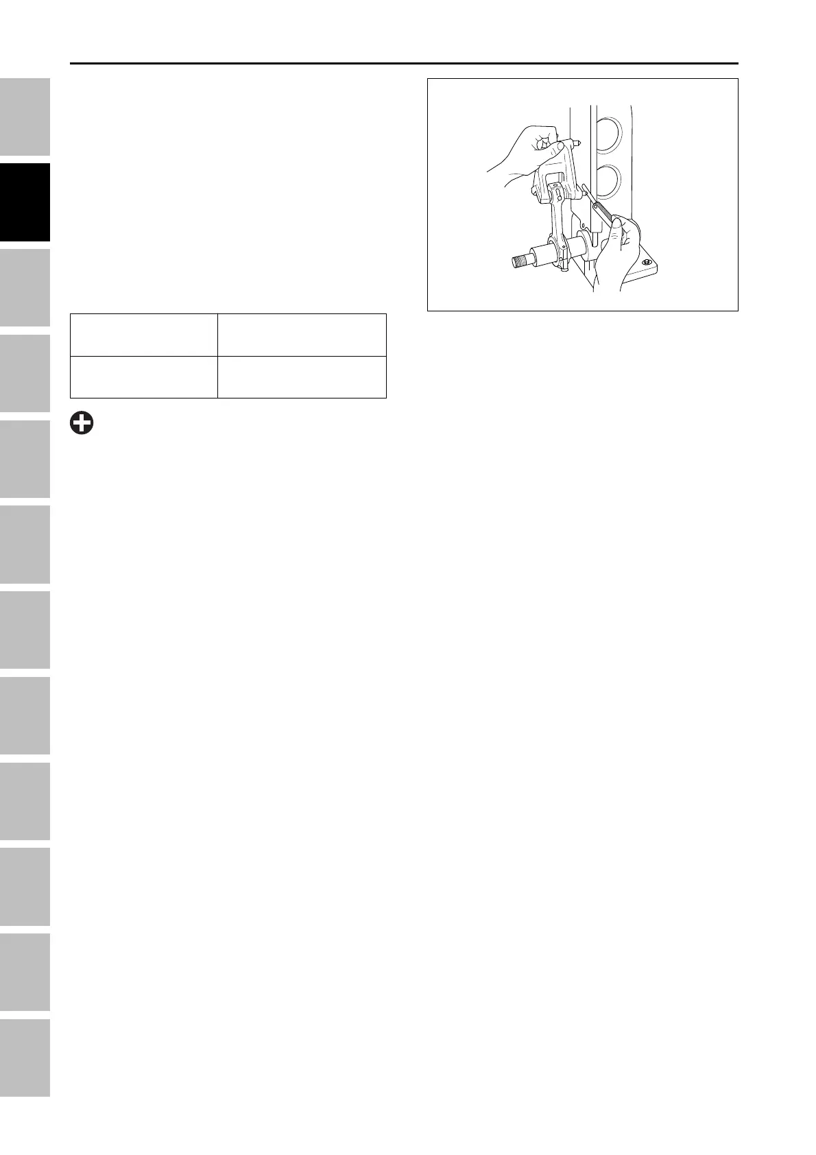
F. CONNECTING ROD ALIGNMENT
1. Remove the connecting rod bearing and install the
bearing cap.
2. Install the piston pin in the connecting rod.
3. Install the connecting rod on the connecting rod
alignment tool.
4. Put a gauge over the piston pin and move it against
the face plate.
5. If the gauge does not fit squarely against the
faceplate, measure the space between the pin of
the gauge and the faceplate.
6. If the measurement exceeds the allowable limit,
replace the connecting rod.
Reference value
Allowable limit
0.02 mm
0.0008 in.
0.05 mm
0.0020 in.
196W2E4A
•
Because the I.D. of the connecting rod small end
bushing is used as the basis for this check, check
it is not worn beforehand.
IMPORTANT
ENGINE - SERVICING