10-43
DS35-W00 May. 2007
CLUTCHCLUTCH
CLUTCHCLUTCH
CLUTCH
TRANSMISSIONTRANSMISSION
TRANSMISSIONTRANSMISSION
TRANSMISSION
ENGINEENGINE
ENGINEENGINE
ENGINE
HSTHST
HSTHST
HST
FRONT AXLEFRONT AXLE
FRONT AXLEFRONT AXLE
FRONT AXLE
STEERINGSTEERING
STEERINGSTEERING
STEERING
BARKEBARKE
BARKEBARKE
BARKE
ELECTRICELECTRIC
ELECTRICELECTRIC
ELECTRIC
INDEXINDEX
INDEXINDEX
INDEX
HYDRAULICHYDRAULIC
HYDRAULICHYDRAULIC
HYDRAULIC
GENERALGENERAL
GENERALGENERAL
GENERAL
REAR AXLEREAR AXLE
REAR AXLEREAR AXLE
REAR AXLE
CK22/CK22H
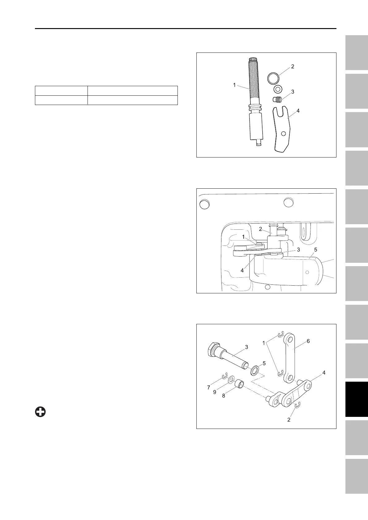
25.Separate links by removing small Cir-clip securing
link to arm. Remove small Cir-clip retaining washer
and roller on arm.
26.Inspect component for wear or damage. Replace
as required.
Installation:
• Installation is the reverse of removal. Be sure to
pay attention to orientation of components when
assembling.
196W976A
(1) Cir-clip (6) Link
(2) Cir-clip (7) Cir-clip
(3) Support pin (8) Roller
(4) Arm (9) Plain washer
(5) Seal washer
19.Measure shaft (1) outside diameter and bore in
housing. Replace if not in specifications.
Shaft (1) Specifications:
21.95 mm (0.864 in.)
22.00 mm (0.866 in.)
O.D.
Bore I.D.
20.Inspect shaft (1), O-ring, stopper screw and lever
for damage or wear. Replace as required.
21.Remove Cir-clip (3) from pin (2).
22.Remove Cir-clip (1) from end of stud (4) on arm (5).
23.Unscrew pin (2) from outside of body making sure
that arm does not bind on shaft of pin during removal.
24.Slide link from stud end and remove link assembly
from body.
196W974A
196W975A
(1) Shaft (3) Stopper
(2) O-ring (4) Lever
(1) Cir-clip
(2) Pin
•
Do not force components during disassembly or
assembly. Clearances are tight and components
must be free to move for depth control mecha-
nism to function correctly.
IMPORTANT
(3) Cir-clip
(4) Stud
(5) Arm
HYDRAULIC SYSTME - SERVICING