2-25
DS35-W00 May. 2007
CLUTCHCLUTCH
CLUTCHCLUTCH
CLUTCH
TRANSMISSIONTRANSMISSION
TRANSMISSIONTRANSMISSION
TRANSMISSION
ENGINEENGINE
ENGINEENGINE
ENGINE
HSTHST
HSTHST
HST
FRONT AXLEFRONT AXLE
FRONT AXLEFRONT AXLE
FRONT AXLE
STEERINGSTEERING
STEERINGSTEERING
STEERING
BARKEBARKE
BARKEBARKE
BARKE
ELECTRICELECTRIC
ELECTRICELECTRIC
ELECTRIC
INDEXINDEX
INDEXINDEX
INDEX
HYDRAULICHYDRAULIC
HYDRAULICHYDRAULIC
HYDRAULIC
GENERALGENERAL
GENERALGENERAL
GENERAL
REAR AXLEREAR AXLE
REAR AXLEREAR AXLE
REAR AXLE
CK22/CK22H
de
D
D
f
Stop
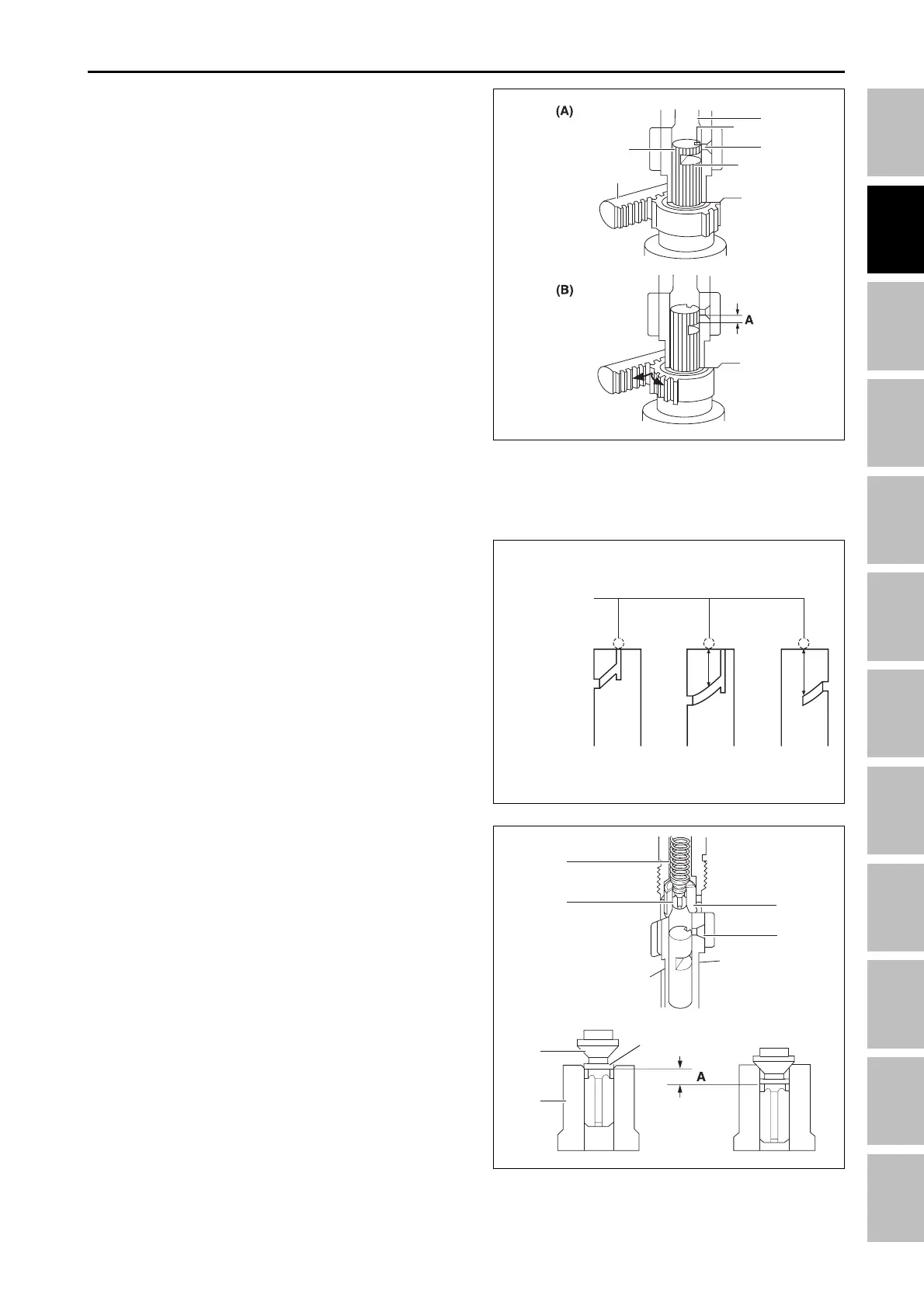
b. Fuel delivery
The plunger is rotated by the control rack and the feed
hole is not aligned with the lengthwise slot. When the
plunger is pushed up, the feed hole is closed by the
plunger. The pressure in the delivery chamber builds
up and forces the fuel to the injection nozzle until the
control groove (6) meets the feed hole. The amount of
the fuel to be forced into the nozzle corresponds to
distance A. In the above figure, the amount of injected
fuel in (c) is larger than the amount of injected fuel in
(b).
T46W240A
(1) Valve spring (4) Fuel chamber
(2) Delivery valve (5) Valve face
(3) Valve seal (6) Relief plunger
D. DELIVERY VALVE
The delivery valve (2) prevents the fuel in the injection
pipe from flowing back into the delivery chamber and
the fuel in the injection nozzle from dribbling after
injection.
The relief plunger (6) sucks the fuel back from the in-
jection pipe to prevent the leakage dribbling and un-
necessary subsequent injection after the major
injection.
The stroke of A corresponds to the amount of fuel sucked
back (35 mm
3
).
T46W241A
C. AMOUNT OF FUEL DELIVERY
a. No fuel delivery
When the control rack (3) is at the engine stop position,
the lengthwise slot (1) on the plunger (2) aligns with
the feed hole (5). The pressure in the delivery chamber
does not build up and no fuel is forced to the injection
nozzle since the delivery chamber (4) is opened to the
feed hole during the entire stroke of the plunger.
(1) Slot (4) Delivery chamber
(2) Plunger (5) Feed hole
(3) Control rack (6) Control groove
T46W239A
4
5
6
2
3
1
Location of fuel
supply hole
Low speed High speed
3
4
1
5
3
2
6
ENGINE - OPERATING PRINCIPLE