52
3.5 Exposure screen
HINT
•••••••••••••••••••••••••••••••••••••••••••••••••••••••••••••••••••••••••••••••••••••••••••••••••••••
• The design of the device icon varies depending on the type of an DR Detector used.
AeroDR 3 1417HD AeroDR 1417HQ
AeroDR 1417S
AeroDR 2 1417HQ
AeroDR 2 1417S
AeroDR 1717HQ AeroDR 1012HQ
• The I/F Cable3 that connects to AeroDR 3 1417HD can also be used as a substitute for the AeroDR UF cable. For this rea-
son, depending on the settings, the AeroDR 3 1417HD device icon may change to the wall stand and table reader icon.
• Display of the device icon changes according to the device status. The meanings of the status to be displayed are listed be-
low.
Exposure is enabled. The DR Detector is not reg-
istered or the DR Detector is
loaded in the wall stand and
table.
This icon is also displayed
when the DR Detector is
turned o.
Error occurs while communi-
cating, or system is not im-
mediately available.
• The device icon color can be changed for each DR Detector depending the settings.
The available color types are as follows:
Blue Orange Light Blue Pink
Each DR Detector retains the color setting information. If the same color is specied for multiple DR Detectors, the following
icon is displayed to indicate the duplication.
For information regarding details on the color setting, contact Konica Minolta technical representatives.
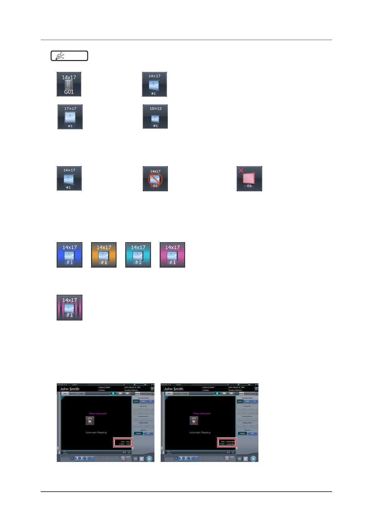
• Displayed contents of the exposure setting and exposure condition icon are dierent depending on the manufacturer and
model of the connected X-ray device.
• The maximum exposure time can be displayed on the right side of the reading conditions, depending on the settings. For
more details, contact Konica Minolta technical representatives.
• The host output size and printer output size can be displayed in the image display area depending on the setting. If the im-
age size is undetermined, [Unspecied] is displayed for the size.
•••••••••••••••••••••••••••••••••••••••••••••••••••••••••••••••••••••••••••••••••••••••••••••••••••••••••••••••••••••