277
7.9 SIGMA stitching exposure
Chapter 7
2
Press [OFF] or the button of the output
size to be changed on the Split Output
Size dialog box.
• The output size is changed.
HINT
•••••••••••••••••••••••••••••••••••••
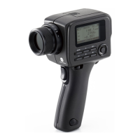
• When output of split images is enabled, a frame ap-
pears on the image to indicate the area of the split im-
age that will be output.
Split output frame
Trimming frame
• The size of the trimming frame changes in accordance
with changes to the size of the image frame so that
images are automatically split into the selected section
size. Images can be split into a maximum of 3 sec-
tions.
• If the split image is smaller than the trimming region,
the entire combined image may not completely fit
within the selected region.
• If the conguration of the split images results in one
image, the split processing is not applied, and the split
output frame does not appear.
•••••••••••••••••••••••••••••••••••••••••••••••••••••
7.9.2 Exposure
The Reina bucky-based exposure method is as fol-
lows. This is an example using three images.
IMPORTANT
•••••••••••••••••••••••••••••••••••••
• For the stitching exposure images, make sure that the
combined parts are combined in the correct positions.
• If there is gap between combined images, manually
adjust the image position of the combined parts using
the viewer screen (for stitching combination position
adjustment). It is also recommended that you arrange
a measure in the combined image part during expo-
sure to conrm the combined parts easier.
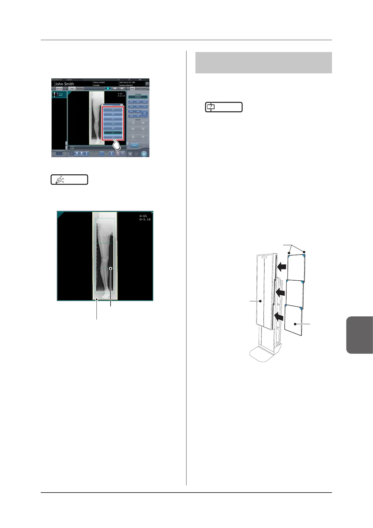
• When loading a CR cassette into a cassette stitching
cabinet, be careful of the following points.
– Load the CR cassette so that the black side of the
plate (the front) is facing towards the patient.
– Load the CR cassette so that the blue corner
blocks are up.
– Check that the whole CR cassette is completely
loaded.
Load with blue
corner blocks up.
Cassette
stitching cabinet
CR
cassette
•••••••••••••••••••••••••••••••••••••••••••••••••••••