93
Chapter 5
5.2 Exposure procedure with DR Detector (Basic connection)
HINT
•••••••••••••••••••••••••••••••••••••
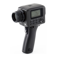
• Linking to the insertion/removal of the DR Detector
into/from the wall stand, the icons inside the applica-
tion bar change as follows.
When the DR Detector is inserted into the wall stand
When the DR Detector is removed from the AeroDR
Battery Charger
• Movement of focus for the image display area is linked
to the state of insertion/removal of the DR Detector
into/from the wall stand.
• When interlock switch is released after receiving the
exposure timing from an X-ray apparatus, the DR
Detector is enabled to allow an operator to press the
exposure switch of the X-ray apparatus. A warning
sounds when the interlock cannot be released (cannot
press the exposure switch).
• X-ray exposure information is acquired automatically
when linked to the X-ray device.
•
The exposure eld is automatically recognized, and dis-
played on the screen as the eective image area. If au-
tomatic recognition of the exposure eld has failed, set it
manually by pressing [Cropping] in the [Image Proc] tab.
• The exposure eld automatic recognition function can
be set for each body part, and the xed eective im-
age area can be selected.
• Congure irradiation elds of at least 5x5 cm for the
following areas.
Infant hip/Front view of lumbar/Side view of lumbar/
Radial position of lumbar/Front view of head/Towne
view of the head/Turkey saddle/Cheekbone axis/Tem-
poromandibular joint/Front view of jawbone/Side view
of jawbone/Front view of the child chest/Side view of
the child chest/Progress observation of child chest/
Front view of infant chest/Side view of infant chest and
abdomen/Progress observation of infant chest and ab-
domen/Newborn chest/Newborn skeleton/Front view
of cervix/Side view of cervix/Radial position of cervix/
Cervix opening/Ribs/Side view of sternum/Radial posi-
tion of sternum/Clavicle/Shoulder joint/Scapula/Ster-
noclavicular joint/Hips/Limbs (excluding radial position
of heel bone)
Congure settings for other areas so that at least one
edge of the irradiation eld is at least 15 cm.
If these conditions are not satised, irradiation elds
sometimes cannot be detected, which would require
reimaging.
•••••••••••••••••••••••••••••••••••••••••••••••••••••
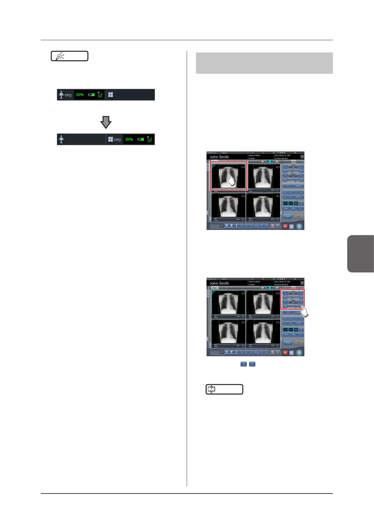
5.2.6 Image adjustment on
the exposure screen
Performs adjustment of exposed images. Basic image
adjustments such as S value/G value, position of ROI
area, etc. can be made on the exposure screen.
z
Change of S value/G value
Change of S value/G value is performed with the fol-
lowing procedure.
1
Select the image for image adjustment.
• The control panel automatically switches to the
[Image Proc] tab. If it does not switch, select the
[Image Proc] tab manually.
2
Adjust the image.
• Pressing [ ] increases or decreases the
value step by step.
IMPORTANT
•••••••••••••••••••••••••••••••••••••
• Calculate the EI value (Exposure Index: Index to
indicate the exposure dose to detector specified in
IEC62494-1) based on Reference signal value in the
grayscale processing and then overlay-display the dif-
ference DI (Deviation Index) between the value and
predened target TI (Target Exposure Index). And, it is
also output to DICOM tag at the time of output to host.
•••••••••••••••••••••••••••••••••••••••••••••••••••••