OPERATION
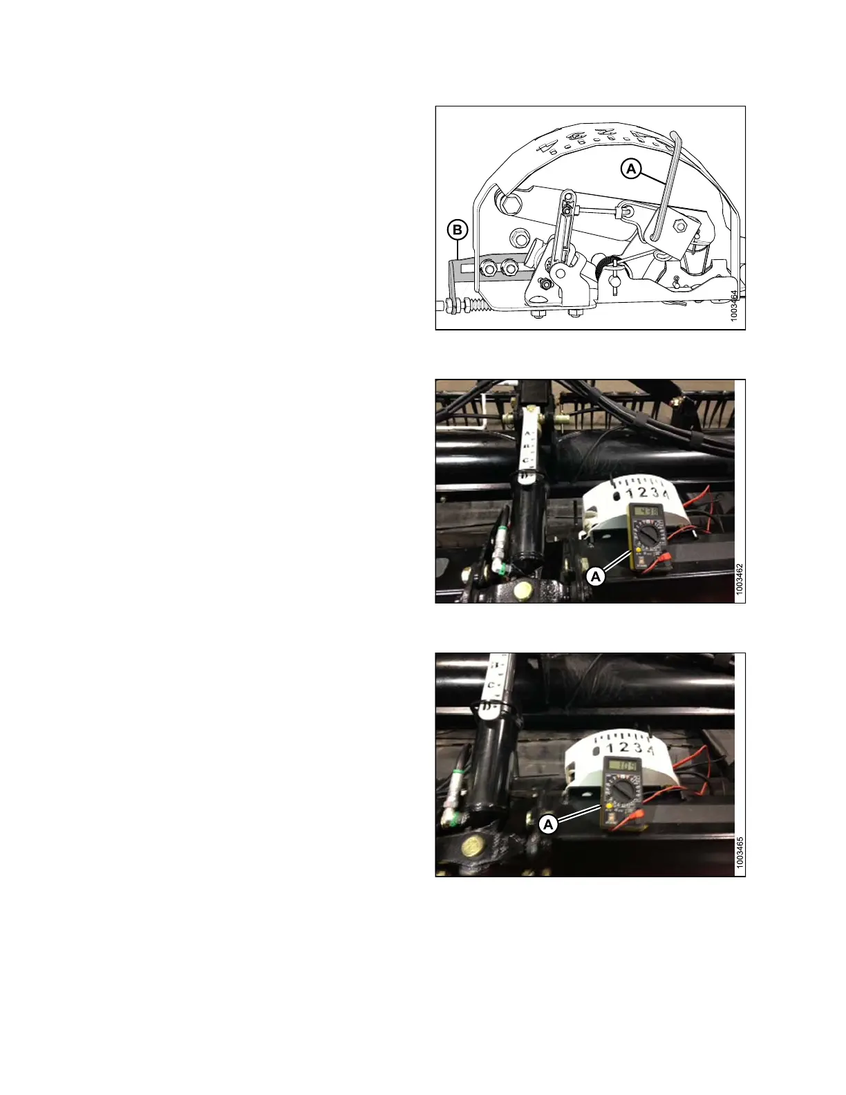
3. Adjust the cable take-up bracket (B) (if necessary) until
the pointer (A) on the float indicator is on ‘0’.
Figure 3.95: Float Indicator Box (Most Common
5 Volt AHHC Sensor Assembly Shown)
4. Using a voltmeter (A), measure the voltage betwee n
theground(Pin2)andsignal(Pin3)wiresattheAHHC
sensor in the float indicator box. It should be at the
high voltage limit for the combine—refer to Table 3.10
Combine Voltage Limits, page 91.
Figure 3.96: Voltmeter between Ground and
Signal Wires
5. Fully lower the combine feeder house, and float the
header up off the down stops (float indicator should be
at ‘4’, and the adapter should be fully separated from
the header).
NOTE:
You ma
y need to hold the header down switch
for a f
ew seconds to ensure the feeder house is
fully
lowered.
6. Usin
g a voltmeter (A), measure the voltage between
the g
round and signal wires at the AHHC sensor in the
float
indicator box. It should be at the low voltage limit
for t
he combine—refer to Table 3.10 Combine Voltage
Limi
ts, page 91.
7. Adj
ust the voltage limits (refer to Adjusting Voltage
Lim
its, page 93) if the sensor voltage is not within the
low
and high limits or if t he range between the low and
hig
h limits is insufficient (refer to Table 3.10 Combine
Vol
tage Limits, page 91).
Figure 3.97: Voltmeter between Ground and
Signal Wires
147695 92 Revision A