MAINTENANCE AND SERVICING
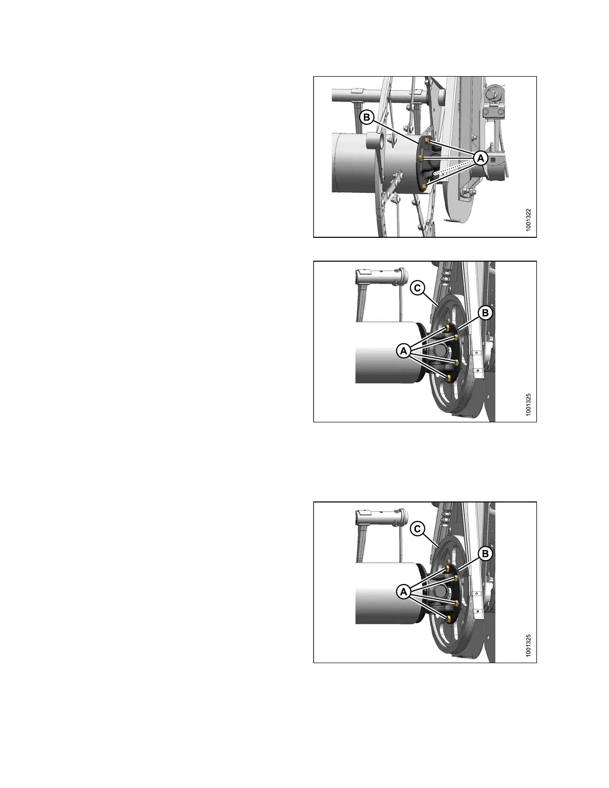
2. Remove four bolts (A) attaching reel tube to U-joint
flange (B) and move reel sideways to disengage stub
shaft from U -joint.
Figure 5.252: U-Joint
3. Remove six bolts (A) attac hin g U-joint flange (B) to
driven sprocket (C).
4. Remove U-joint.
NOTE:
Right-hand reel may need to be moved sideways for
U-joint to clear reel tube.
Figure 5.253: U-Joint
Installing Double Reel U-Joint
To inst
all the U-joint, follow these steps:
NOTE:
Right-hand reel may need to be moved sideways for
U-joint to clear reel tube.
1. Posit
ion U-joint flange (B) onto driven sprocket (C) as
shown
. Install six bolts (A) and hand-tighten. Do NOT
torq
ue at this time.
Figure 5.254: U-Joint
147695 376 Revision A