OPERATION
Figure 3.100: Most Common 5 Volt AHHC
Sensor Assembly
3.8.2 Challenger 6 and 7 Series Combines
Checking Voltage Range from the Combine Cab ( Challenger 6 and 7 Se ries)
NOTE:
Changes may have been made to the combine controls or display since this document was published. Refer to
the combine operator’s manual for updates.
To check the sensor’s output voltage range from the combine cab, follow these steps:
1. Position the header 6 in. (150 mm) above the ground, and unlock the adapter float.
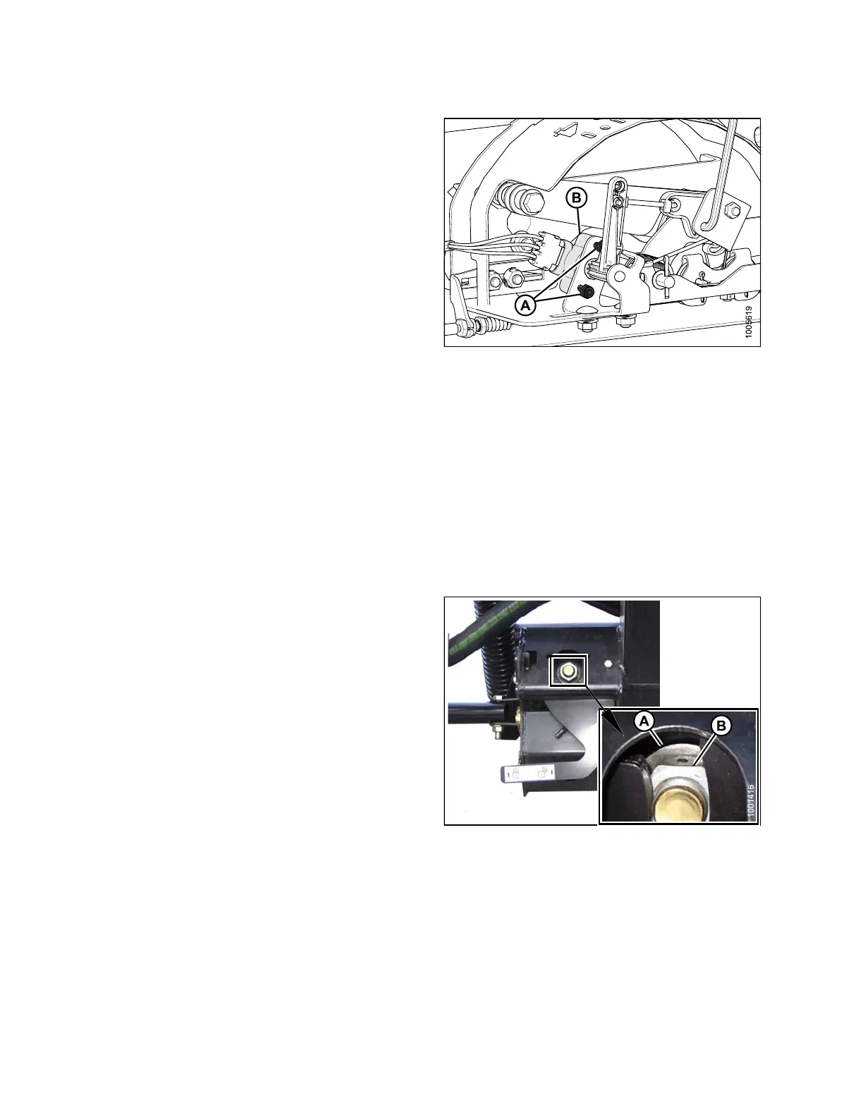
2. Check that float lock linkage is on down stops
(washer [A] and nut [B] cannot be moved) at both
locations.
NOTE:
If the header is not on down stops during the next
two steps, the voltage may go out of range during
operation causing a malfunction of the AHHC system.
Figure 3.101: Float Lock
147695 94 Revision A