MAINTENANCE AND SERVICING
NOTE:
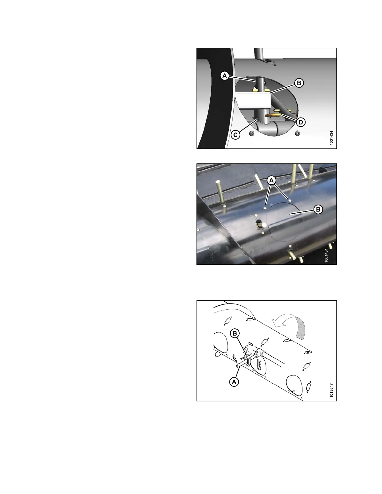
The #6 tine (A) must also be inserted through the
square tube (B).
4. Secure tine (A
) in bushing (C) with hairpin (D). Install
hairpin with c
losed end leading with respect to auger
forward rotat
ion.
Figure 5.73: Tine
5. Replace access cover (B), and secure with screws (A).
Coat screws with Loctite
®
#243 (or equivalent), and
torque to 75 in·lbf (8.5 N·m).
Figure 5.74: Auger
Replacing Auger Tine Guides
1. Remove
tine (B) and plastic guide (D). Refer to
Removi
ng Feed Auger Tines, page 293.
Figure 5.75: Auger
147695 296 Revision A