OPERATION
3.9 Levelling the Header
The adapter is factory-set to provide the proper level for the header, and should not normally require adjustment.
If the header is NOT lev el, perform the following checks prior to adjusting the le ve lling linka ges:
• Check comb ine tire pressures.
• Check that the combine feeder house is level. Refer to your combine operator ’s manual for instructions.
• Check that top of adapter is level and parallel with the feeder house.
NOTE:
The adapter
float spring s are not used to level the he ader.
To make fine adjustments to header levelling, follow
these steps:
1. Park combine on level ground.
2. Set header approximately 6 in. (150 mm) off ground,
and check that float linkage is against down stops.
Note high and low end of header.
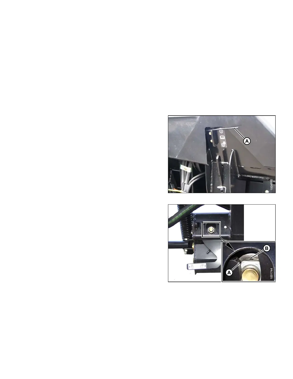
3. Set wing float lock (A) to engaged. Refer to 5.16 .1
Checking Wing Balance, page 396 and 5. 16.2
Adjusting Wing B alance, page 401.
4. Check a nd set float adjustment. Refer to Checking and
Adjusting Header Float, page 58.
Figure 3.263: Wing Lock
5. Adjust level with nu t (A) at e ac h floa t lock as follows.
Use s mall adjustments (1/4–1/2 turn), and adjust each
side equally but in opposite directions:
NOTE:
Setscrew (B) does not require loosening for
adjustments up to one-half turn of nut (A).
a. Turn low-side nut clockwise to raise header.
b. Turn high-side nut counterclockwise to
lower header.
NOTE
:
Adju
stment of more than two turns in either
dire
ction may adversely affect header float.
Figure 3.264: Float Lock
147695 173 Revision A