OPERATION
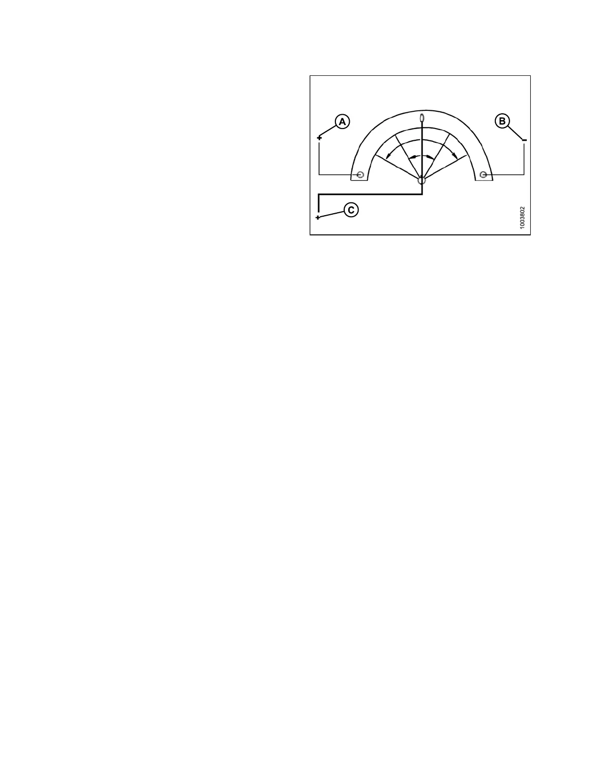
In addition to the power (A) and ground (B) wires, a signal
wire (C) is connected internally to a movab le wiper that is
attachedto an externalarm and sweeps the high resistance
filament band. As the external arm is rotated and the wiper
is moved toward or away from the power wire connection,
the measured resistance at the signal wire (C) changes.
The resistance m easured across the signal and ground
wires should increase uniformly from a low (80–100 ohms)
to a high (800–1200 ohms). This can be observed if an
ohmmeter is connected across the signal and power wires
and the sensor shaft rotated. W hen an input voltage is
applied to the high resistance filament band through the
power wire (A), the output (or ‘measured’) voltage in the
signal wire (C) is c hanged by this variable resistance.
NOTE:
Ground and power wires may differ depending
on combin e.
Figure 3.262: Power, Ground, and Signal Wires
147695
1
72
Revision A