MAINTENANCE AN D SERVICING
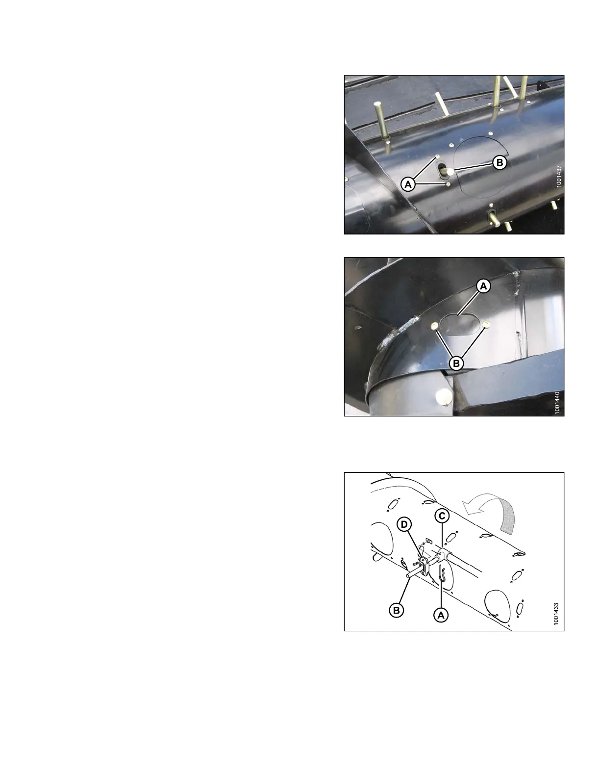
7. Remove screws (A) securing plastic guide (B) to auger,
and remove guide from inside auger.
Figure 5.70: Auger
8. Position cover (A) from inside auger over hole, and
secure with screws (B). Coat screws with Loctite
®
#243
(or equivalent), and torque to 75 in·lbf (8.5 N·m).
Figure 5.71: Auger
Installing Feed Auger Tines
1. Remove
access cover (if applicable ).
2. Insert
tine (B) through plastic guide (D) from inside
the au
ger.
3. Inser
t tine into bushing (C).
Figure 5.72: Tine
A-Ha
irpin
B-Ti
ne
C - Bushing D - Plastic Guide
147695 295 Revision A