OPERATION
18. Return torque w rench (A) to storage location at
right-hand side of adapter frame.
Figure 3.46: Torque Wrench
Locking/Unlocking Header Float
The functi
on of the header float locks is to lock and unlock the header float system. There are two locks—one on
each side
of the adapter.
IMPORTAN T:
The float locks must be engaged when the header is being transported with the adapter attached so that there is
no relative movement between the adapter and header during transport. The float locks m ust also be locked
during detachment from the combine to allow the feeder house to release the adapter.
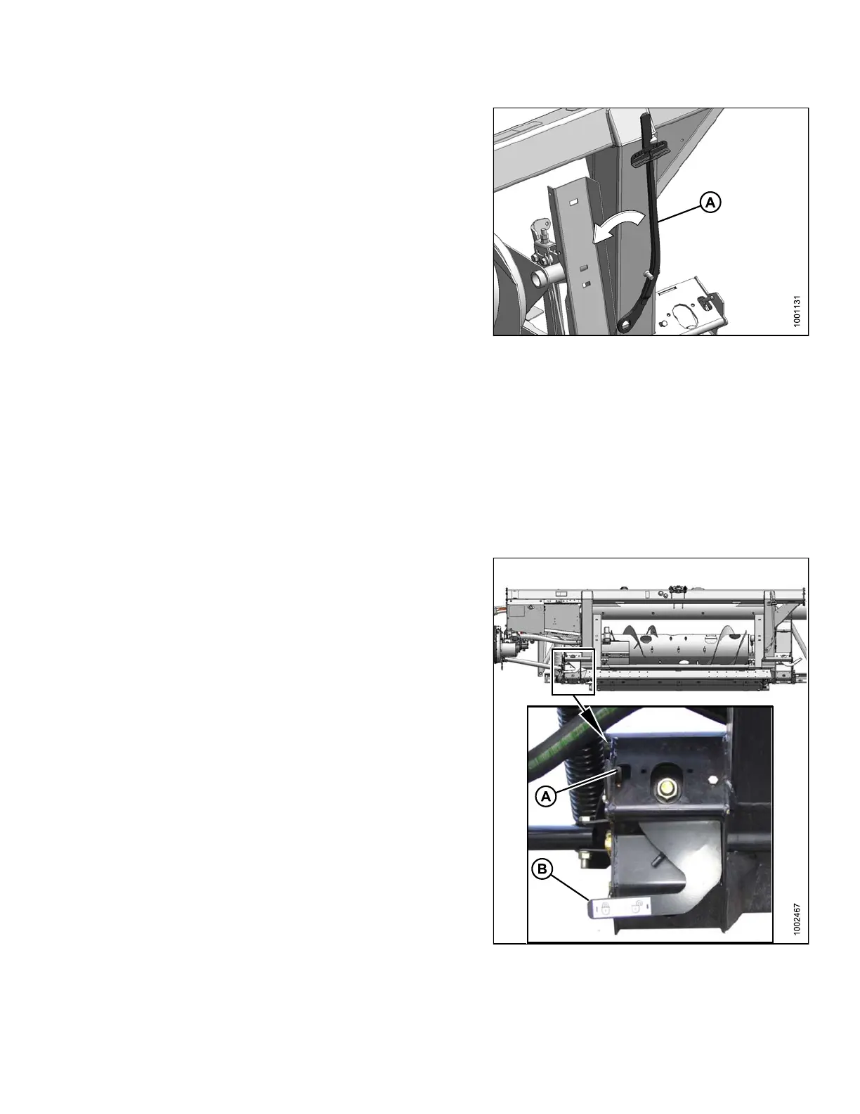
To disengage float locks (unlock), move latch (A)
downward, and move lever (B) at each lock to lowest
position. In this position, the header is unlocked, and can
float with respect to the adapter.
To engage float locks (lock), move lever (B) up to its
highest position. In this position, the header cannot move
with respect to the adapter.
Figure 3.47: Float Lock
147695 63 Revision A