OPERATION
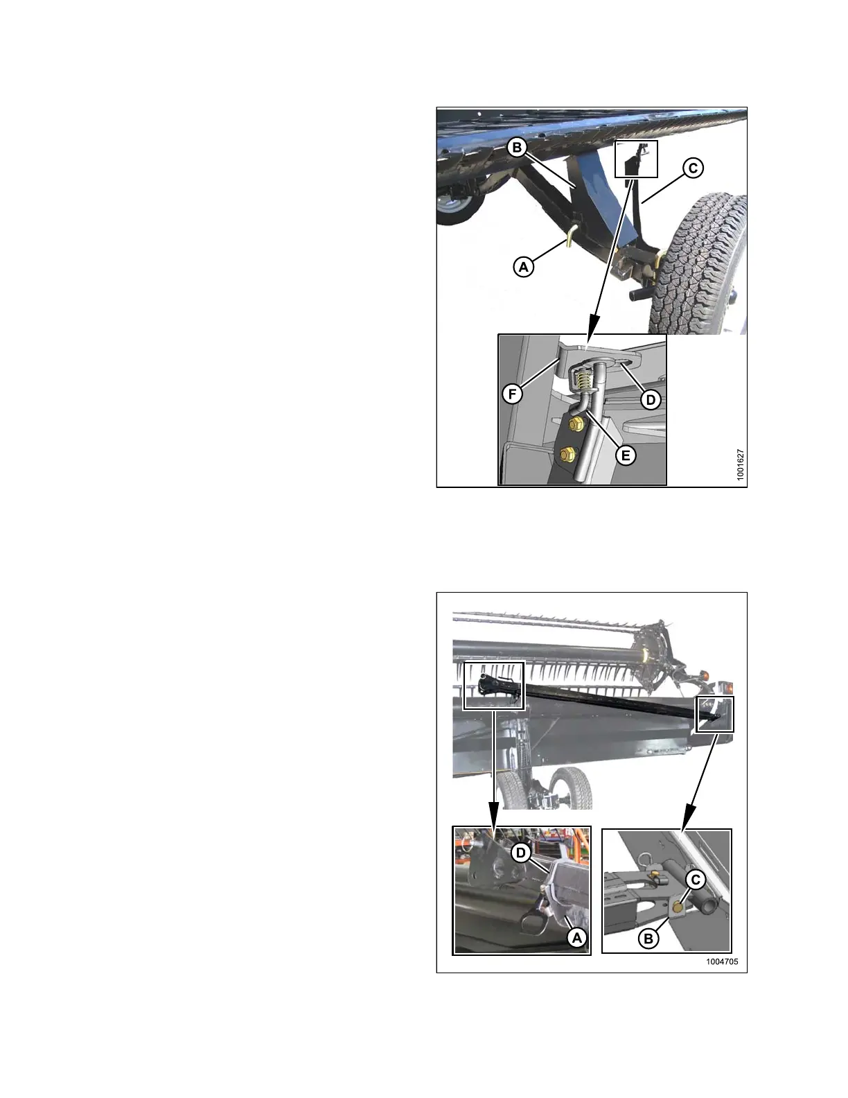
11. Remove pin (A), raise support (B) to position shown,
and r ein se rt pin (A).
IMPORTANT:
Ensure pin (A) engages the tube on the axle.
12. Swing brace (C) into position as shown and insert
brace into slot (D) behin d c utterbar. Pos itio n b race so
that pin (E) engages hole in bracket (F). Right-hand
wheel is now in Transport position.
13. Disengage the header cylinder lift stops.
14. Detach the header’s hydraulic and electrical
connections from the combine. Refer to 4 Header
Attachment/Detachment, page 197.
15. Start combine and lower header to the ground.
Figure 3.
291: Right Rear Wheel
Attachi
ng Tow-Bar
The tow-bar consists of two sections which make storage and handling easier.
1. On the right side of the header, unhook rubber strap (D)
on cradle (A).
2. Remove clevis pin (C). Detach tube end from
support (B).
3. Replace cle vis pin .
4. Lift inner half of tow-bar off of header, and place it near
the left side of the header.
Fi
gure 3.292: Tow-Bar
147695 192 Revision A