OPERATION
3.7.2 Header Float
The header fl oa
t system reduces the ground pr essure at the cutterbar and allo ws it to m ore easily follow the
ground and qui
ckly respond to sudden ground contour changes or obstacles.
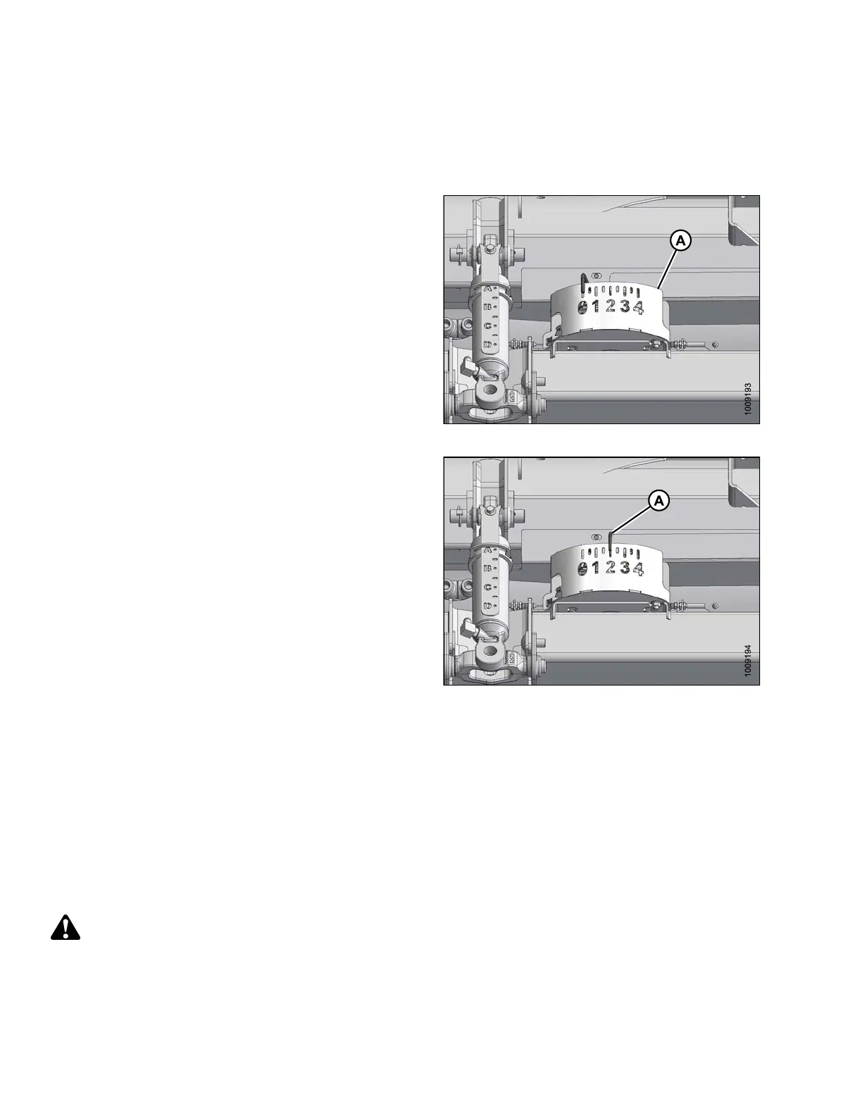
Header float is
indicated on the CA25 float indicator (A) and
the values 0 t
o 4 represent the force of the cutterbar on the
ground, with
‘0’ being the least and ‘4’ th e highest.
The m aximum f
orce is determined by the tension on the
adapter float
springs which are adjustable. The tension
is fa ctory s
et but can be changed to suit field and crop
conditions
. Refer to Checking and Adjusting Header Float,
page 58.
TheFD75com
bine header performs best with minimum
ground pre
ssure, under normal conditions. Readjust the
float if add
ing optional attachments that affect the weight of
the header
.
Figure 3.34: Float Indicator
1. To set the
float for cutting on the ground:
a. Ensure th
at the header fl oat locks are disengaged.
Refer to L
ocking/Unlocking Header Float, page 63.
b. Lower fee
der h ouse with combine header controls
until flo
at indicator (A) reaches the desired float
value (c
utterbar ground force). Use “2” initially and
adjust a
ccordingly.
Figure 3.35: Cutting on the Ground
2. To set t
he float for cutting off the ground:
a. Set up
the stabilize r wheels. Refer to Cutting Off
the Gr
ound, page 52.
b. Note t
he float value on the float indicator and
maint
ain this value during operation, disregarding
mino
r fluctuat ions on the indic ator.
Checking a nd Adjusting Header Float
To check and
adjust th e header float, follow these steps:
DANGER
To avoid bodily injury or death from unexpected start-up of machine, always stop engine and remove key
from ignition before leaving operator ’s seat for any reason.
147695 58 Revision A