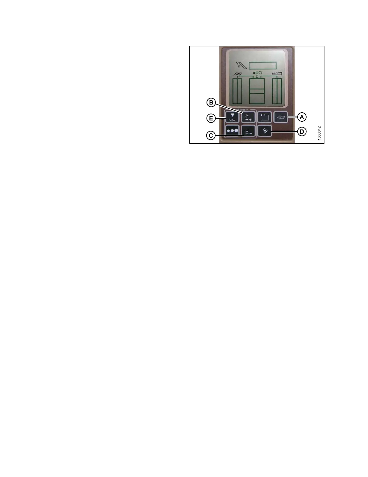
OPERATION
1. Press the DIAGNOSTIC button (A) on the monitor –
DIA appears on the monitor.
2. Press the UP button (B) until EO1 appears on
the monitor, and press ENTER (D) – this is the
header adjustment.
3. Press the UP (B) or DOWN (C) button until
‘112’ is displayed on the monitor – this is your
sensitivity setting.
NOTE:
The lower the
reading, the higher the sensitivity.
Ideal opera
ting range is typically between 50–80.
4. Press ENTER
(D) to select ‘112’ as the sensitivity
setting (th
is will allow you to change the first digit of
the number
sequence).
5. Press UP (B
) or DOWN (C) until the desire d number
is display
ed, t he n press the CAL (E) button. This will
bring you t
o the second digit. Repeat this procedure
until the
desired setting is ac hie ve d .
6. Press ENT
ER (D) to save changes.
NOTE:
The numbers depicted on the displays in these
illustrations ar e fo r refe rence purpose s only;
they are not intended to represent the specific
settings for your equipment.
Figure 3.182: Combine Display
Adjusting the Thre shold for the Drop Rate Valve (John Deere 60 S eries)
This adjusts the point at which the restrictor valve opens allow ing full flow to the lift cylinde rs.
NOTE:
Changes may ha
ve been made to the combine controls or display since this document was published. Refer to
the combine o
perator’s manual for updates.
147695 136 Revision A