OPERATION
7. Fully lower the combine feeder house adapter should
be fully separated from the header).
NOTE:
You m ay need to
hold the header down switch
for a few secon
ds to ensure the feeder house is
fully lowered
.
8. Read vo lta g e
.
9. Raise header
so cutterbar is 6 in. (150 mm) off
the ground.
10. Read voltag
e.
11. Adjust the v
oltage limits (refer to Adjusting Voltage
Limits, pag
e93) if the sensor voltage is not within the
low and hig
h limits or if the rang e between the low and
high limit
s is insufficient (refer to Table 3.10 Combine
Voltage Li
mits, page 91).
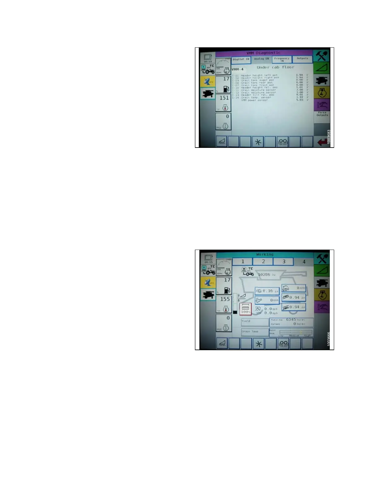
Figure 3.105: Challenger Combine Display
Engaging the Auto Header Height Control ( Ch allenger 6 S eries)
NOTE:
Changes may have
been made to the combine controls or display since this document was published. Refer to
the combine oper
ator’s manual for updates.
The following system components are required in order for the Auto Header Height Control (AHHC) to work:
• Main module (PCB board) and header driver module
(PCB board) mounted in card box in Fuse Panel
Module (FP).
• Multi-Function Control Handle operator inputs.
• Operator inputs mounted in the control console module
(CC) panel.
NOTE:
In addition to the above components, the electro
hydraulic header lift control valve also is an integral part
of the system.
Engage the AH
HC as follows:
1. Scroll thro
ugh the header control options on the
combine dis
play using the header control switch until
the AHHC ico
n is disp layed in the first message box.
The AHHC wil
l adjust the header height in relation
to the groun
d according to the height setting and
sensitivi
ty setting.
Figure 3.106
: Challenger Combine Display
147695 96 Revision A