OPERATION
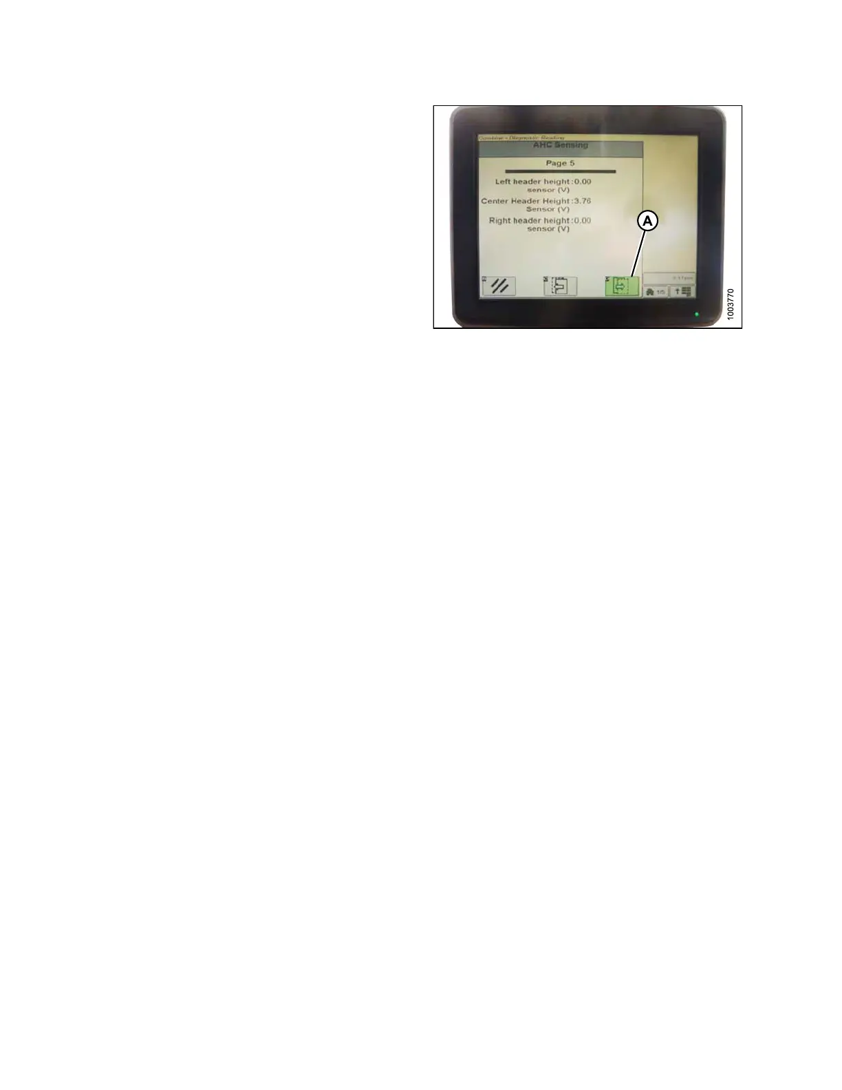
9. Press icon (A) until it reads ‘Page 5’ near the top of
the page and the following sensor readings appear:
• LEFT HEADER HEIGHT
• CEN TER HEADER HEIGHT
• RIGHT HEADER HEIGHT
A reading is displayed for only the center header
height sensor. On the MacDon header, there is only
one sensor located in the float indicator box on top of
the CA25.
Figure 3.204: Combine Display
10. Ensure he a der float is unlocked.
11. Start the combine and fully lower feeder house to
the ground.
NOTE:
You may nee
d to h old the header down switch
for a few s
econds to ensure the feeder house is
fully low
ered.
12. Check the
sensor reading on the monitor.
13. Adjust t
he voltage limits (refer to Adjus ting Voltage
Limits,
page 93) if the sensor voltage is not within the
low and h
igh limits or if the rang e between the low and
high lim
its is insufficient (refer to Table 3.10 Combine
Voltage
Limits, page 91).
Calibrating the Auto Header Height Control (John De ere S Series)
For best perfo
rmance of the Auto Header Height Control (AHHC), perform these procedures with the center-link
settoD.Whens
etup and calibration are complete, adjust the center-link back to desired header angle. Refer to
3.7.3 Head er A
ngle, page 66.
NOTE:
Changes may have been made to the combine controls or display since this document was published. Refer to
the combine operator’s manual for updates.
To calibrat
e the AHHC, follow these steps:
1. Ensure cent
er-linkissettoD.
2. Rest header
on down stops and unlock adapter float.
3. Place win g
s in locked position.
147695 146 Revision A