MAINTENANCE AND SERVICING
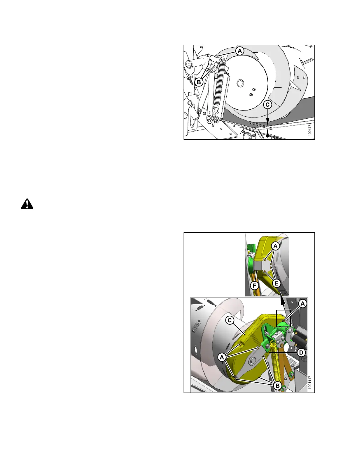
6. Loosen two nuts (B).
7. Set clearance (C) to 3/16–3/8 in. (5–10 mm) with
adjuster bolt (A). Turn bolt clockwise to increase
clearance, counterclockwise to decrease.
NOTE:
The clearance increases to 1–1-1/2 in. (25–40 mm)
when the center-link fully retracts for a flatter
header angle.
8. Repeat Steps
6., page 286 and 7., page 286 for other
end of auger
.
9. Tighten nut
s (B) on both ends of feed auger. Torque
nuts to 79–8
7ft·lbf (106–118 N·m).
Figure 5.50: Auger Clearance
5.7.2 Adjusting Auger Drive Chain Tension
The auger i
s chain-driven from the adapter drive system by a sprocket that is attached to side of the auger.
To adjust c
hain slack, follow these steps:
DANGER
To avoid bodily injury or death from unexpected start-up of machine, always stop engine and remove key
from ignition before leaving operator ’s seat for any reason.
1. Detach header from combine. For instructions, refer to
4 Header Attachment/Detachment, page 197.
2. Remove the six bolts (A) that secure the top cover on
the auger chain case.
3. Remove the three bolts (B) and loosen two bolts (E)
that secure the bottom cover.
4. Remove cover retainer (F).
5. Rotate top cover (C) and bottom cover (D) forward
to remove .
Figure 5.51: Auger Drive
147695 286 Revision A