MAINTENANCE AND SERVICING
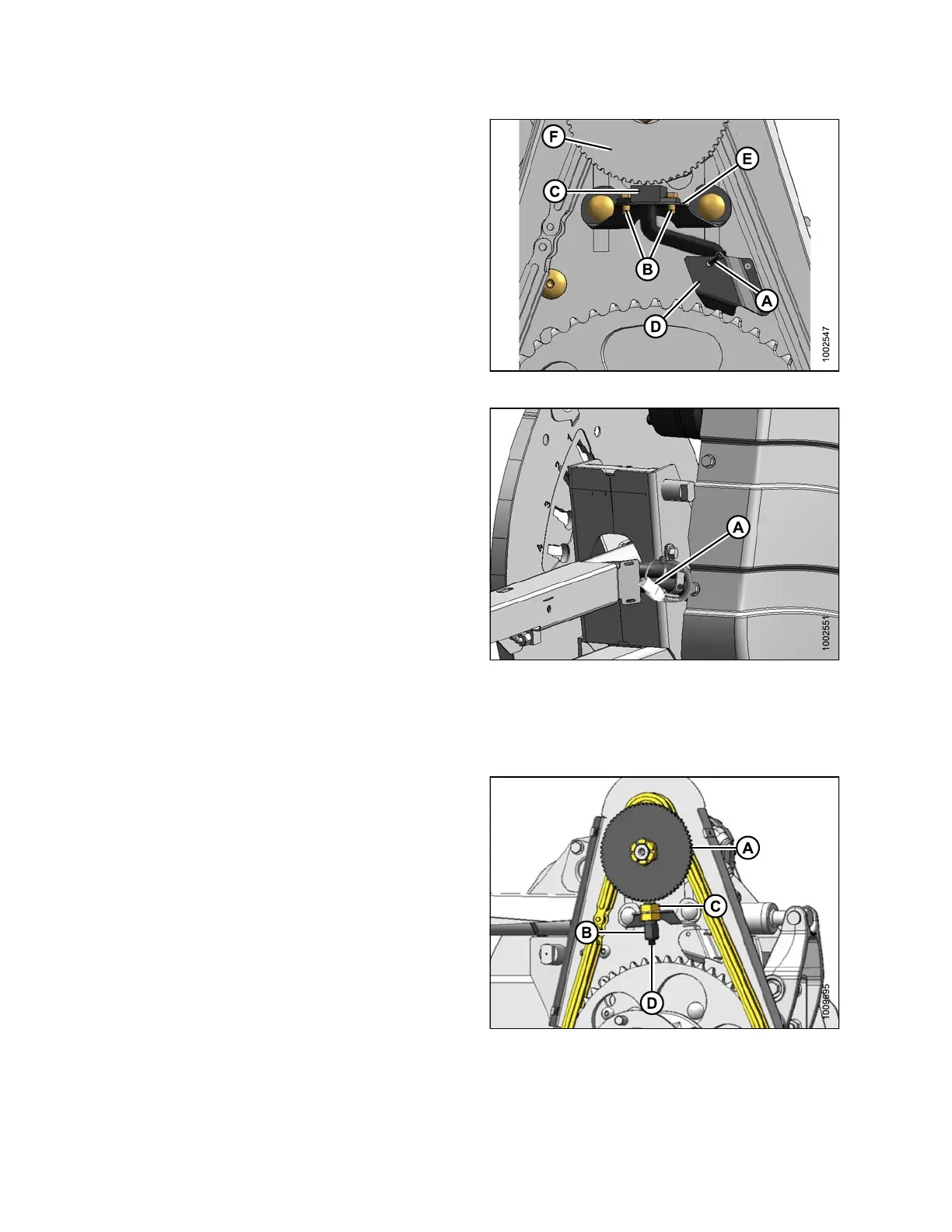
2. Cut cable tie (A) securing harness to cover.
3. Remove screws (B) and remove sensor (C) and
harness. Bend cover (D) (if nec es sary ) to remove
harness.
4. Feed wire of new sen so r be h ind cover (D ) thro ug h
chain cas e.
5. Locate new sensor in support (E) and attach with two
screws (B).
6. Adjust gap between sensor disc (F) and sensor (C) to
0.02 in. (0.5 m m).
Figure 5.286: Speed Sensor
7. Connect to harness at (A).
IMPORTANT:
Ensure sensor electrical harness does NOT contact
chain or sprocket.
8. Reinstall cover. Refer to Insta lling Drive Cover, page
388.
Figure 5.287: Electrical Harness
Replacing John Deere Se nsor
To repl
ace the reel speed sensor for a John Deere combine, follow these steps:
1. Discon
nect connector (D).
2. Remov
e top nut (C) and remove sensor (B).
3. Remov
e top nut from new sensor a nd position sen so r
in sup
port. Secure with top nut (C).
4. Adju
st gap between sensor disc (A) and sensor (B) to
1/8 i
n. (3 mm) with nut (C).
5. Conn
ect to harness at (D).
IMPORTANT:
Ensure sensor electrical harness does NOT contact
chain or sprocket.
6. Rei
nstall cover. Refer to Installing Drive Cover, p age
388.
Figure 5.288: Speed Sensor
147695 390 Revision A