OPERATION
3.8.5 Gleaner
R62/R72 Combines
Determining S
ystem Requirements (Gleaner R62/R72)
NOTE:
Changes may have been made to the combine controls or display since this document was published. Refer to
the combine operator’s manual for updates.
The f ollo wi
ng system components are required in order for the Auto Header Height Control (AHHC) system to work:
• Main module
(PCB board) and header driver m odule (PCB board) mounted in card box in Fuse Panel Module (FP).
•Multi-Func
tion Control Handle operator inputs.
•Operatori
nputs mounted in the control console module (CC) panel.
NOTE:
In addition to the above components, the electro hydraulic header lift control valve also is an integral part of
the system.
Calibrating the Auto Header Height Control (Gleaner R62/R72)
For best
performance of the Auto Header Height Control (AHHC), perform these procedures with the center-link
set to D.
When setup and calibration are complete, adjust the center-link back to desired header angle. Refer to
3.7.3 He
ader Angle, page 66.
NOTE:
Changes may have been made to the combine controls or display since this document was published. Refer to
the combine operator’s manual for updates.
To cali
brate the AHHC, follow these steps:
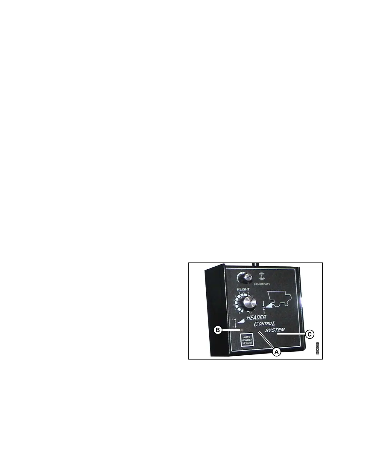
1. Ensure
center-link is set to D.
2. Start
the combine engine, and press and hold
the hi
dden C1 button (A) until the LED light (B)
flashe
sbriefly.
3. Lower
the feeder house as far as it will go.
4. Pres
s and hold the hidden L2 button (C) until the
LED l
ight (B) flashes briefly. The AHHC system is
now c
alibrated.
Fig
ure 3.148: Combine Header Control System
Se
tting the Sensitivity of the Auto Header Height Control (Gleaner R62/R72 Series)
NOTE:
Changes may have been made to the combine controls or display since this document was published. Refer to
the combine operator’s manual for updates.
147695
1
14
Revision A