REFERENCE
8.1.3 Metric B
olt Specifications Bolting into Cast Aluminum
Table 8.9 Metric Bolt Bolting into Cast Aluminu m
Bolt Torque
8.8
(Cast Alumin
um)
10.9
(Cast Alumin
um)
Nominal
Size (A)
ft·lbf
N·m
ft·lbf
N·m
M3
––
1
–
M4
––
2.6 4
M5
––
5.5
8
M6 6 9 9 12
M8 14 20 20 28
M10 28 40 40
55
M12 52 70 73 100
M14
––––
M16
––––
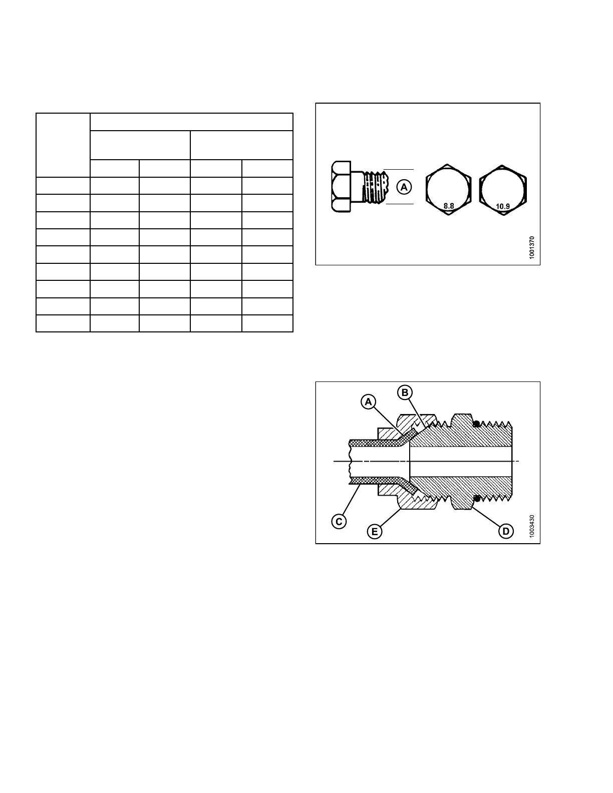
Figure 8.9: Bolt Grades
8.1.4 Flare-Type H ydraulic Fittings
1. Check flare (A) and flare seat (B) for defects that might
cause leakage.
2. Aligntube(C)withfitting (D) and thread nut (E) onto
fitting withou t lubrication until contact has been made
between the flared surfaces.
3. Torque the fitting nut (E) to the specified number of
flats from finger tight (FFFT) or to a given torque v alue
in Table 8.10 Flare-Type Hydraulic Tube Fittings, page
439.
4. Use two wrenches to prevent fitting (D) from r otating.
Place one wrench on the fitting body (D) and tighten
nut (E) with the other wrench to the torque shown.
5. Assess the final condition of the connection.
Figure 8.10
: Hydraulic Fitting
147695 438 Revision A