MAINTENANCE AN D SERVICING
NOTE:
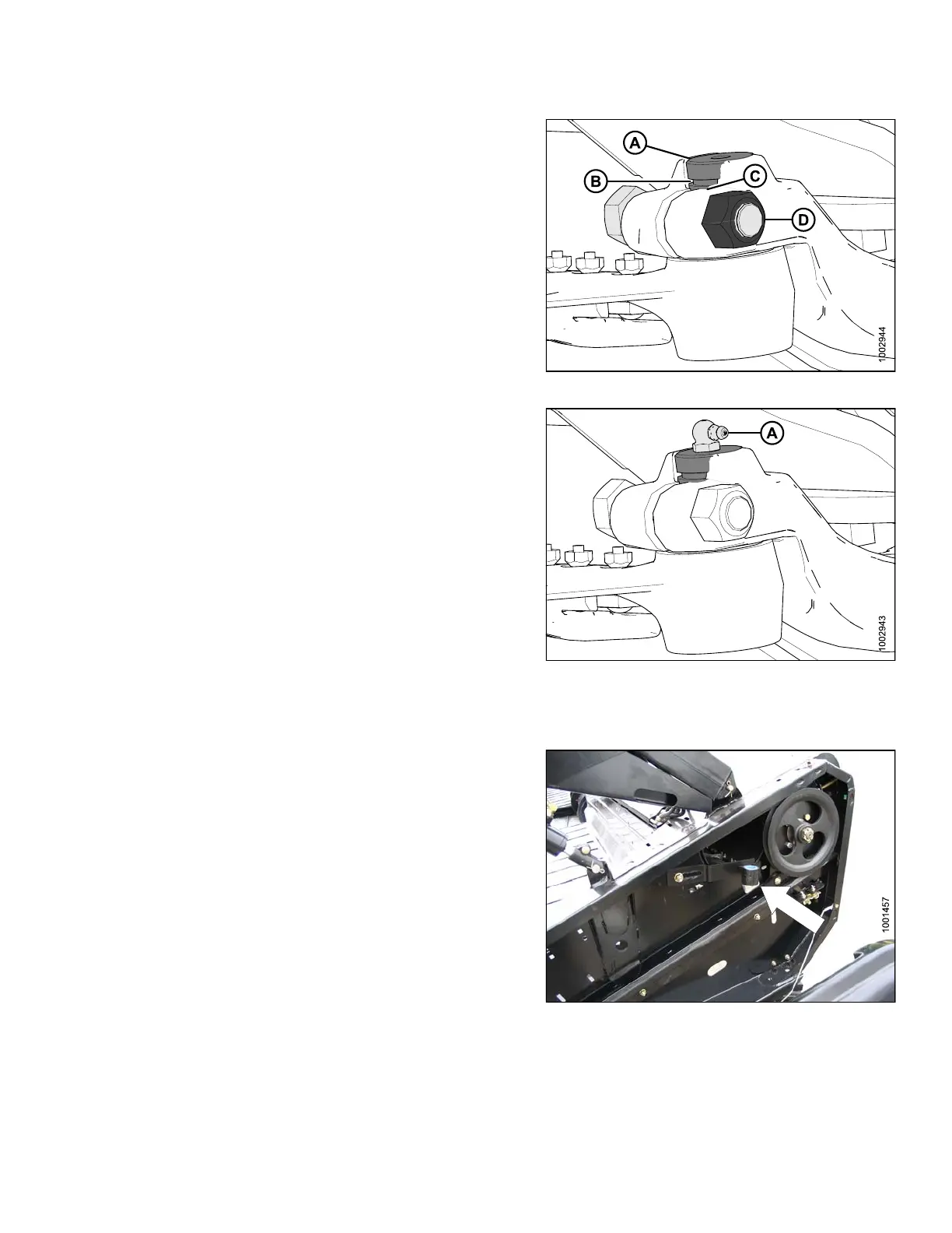
For ease of removing or installing knifehead pin,
remove greas e ze rk from pin.
2. Install knifehead pin (A) through the output arm and
into the knifehead.
3. Set groove (B) in knifehead pin 1/16 in. (1.5 mm)
above (C). Install the 5/8 in. x 3 hex head bolt (D) and
nut and torque to 160 ft·lbf (217 N ·m).
Figure 5.88: Knifehead
4. Install grease zerk (A) into the knifehead pin, turn the
grease zerk for easy access.
IMPORTAN T:
Grease knifehead just enough to start a slight
downward movement of knifehead. Over-greasing
will lea d to knife misalignm e nt of the knife which
causes guards to overheat and drive systems
to overload.
Figure 5.89: Knifehead
5.8.6 Spare Knife
A spare knife m ay be stored in the header frame tube at
the left end. Ensure knife is secured in place.
Figu
re 5.90: Spare Knife
5.8
.7 Knife Guards
Check DAILY that guards are aligned and that knife sections are contacting shear surface of each guard.
147695 303 Revision A