OPERATION
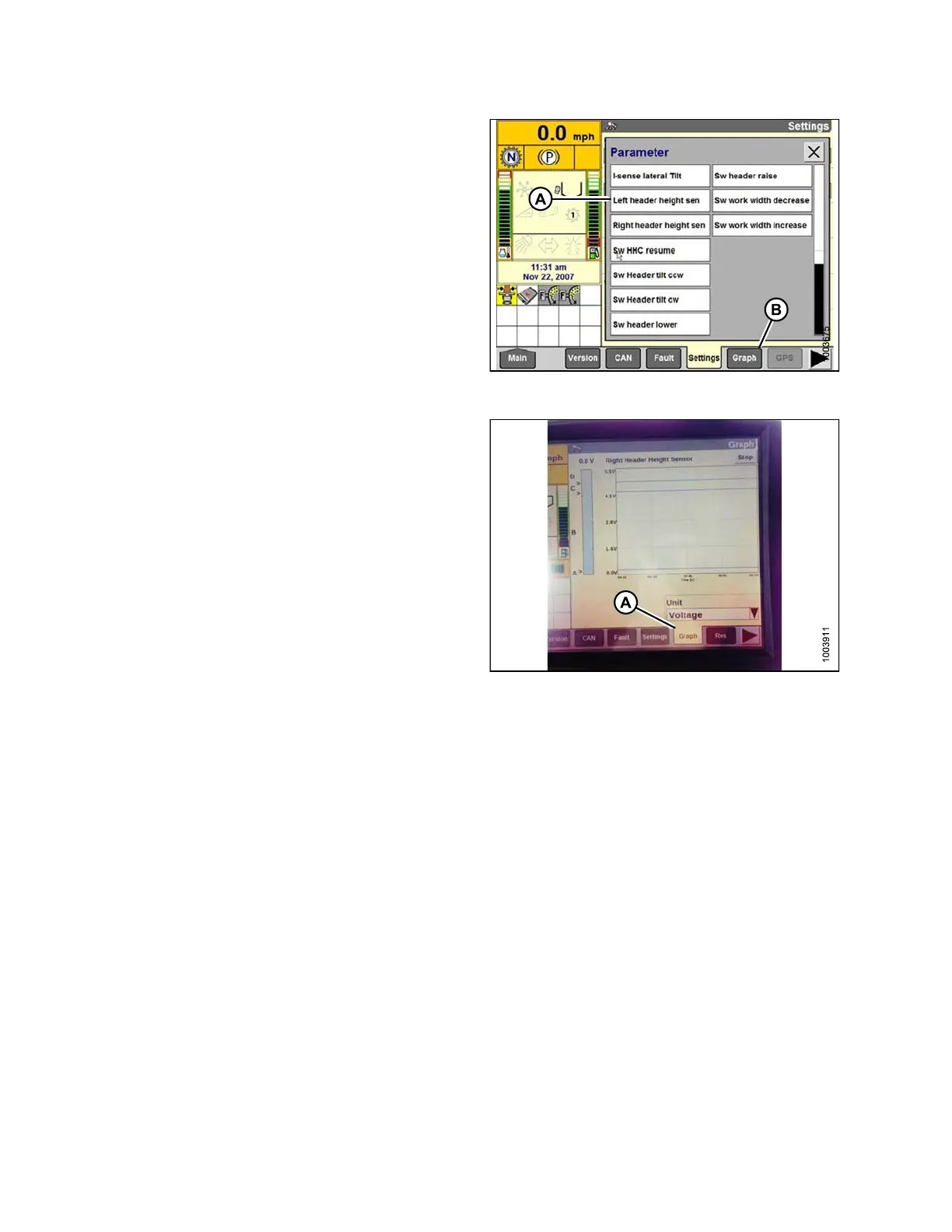
9. Select LEFT HEADER HEIGHT SEN (A), and then
select the GRAPH bu tton (B). The exact voltage is
displayed at top of screen. Raise and lower the header
to see the full range of voltage readings.
10. Adjust the voltage limits (refer to Adjusting Voltage
Limits, page 93) if the sensor voltage is not within the
low and high limits or if the range between the low and
high limits is insufficient (refer to Table 3.10 Combine
Voltage Limits, page 91).
Figure 3.138: Case IH Combine Display
Figure 3.139: Case IH Combine Display
Calibrating the Auto Header Height Control (Case IH 5130/6130/7130, 7010/8010;
7120/8120/9120; 7230/8230/9230)
For best performance of the Auto Header Height Control (AHHC), perform these procedures with the center-link
set to D. When setup and calibration are complete, adjust the center-link back to desired header angle. Refer to
3.7.3 Head er A ngle, page 66.
NOTE
:
This
procedure applies to combines with a software version below 28.00. For instructions on calibrating the AHHC
for c
ombines with software versio n 28.0 0 or above, refer to Calibrating the Auto Header Height Control System
(Cas
e Combines with Version 28.00 Software), page 112.
NOTE:
Changes may have been made to the combine controls or display since this document was published. Refer to
the combine operator’s manual for updates.
To c
alibrate th e AH HC, follow thes e steps:
147695 110 Revision A